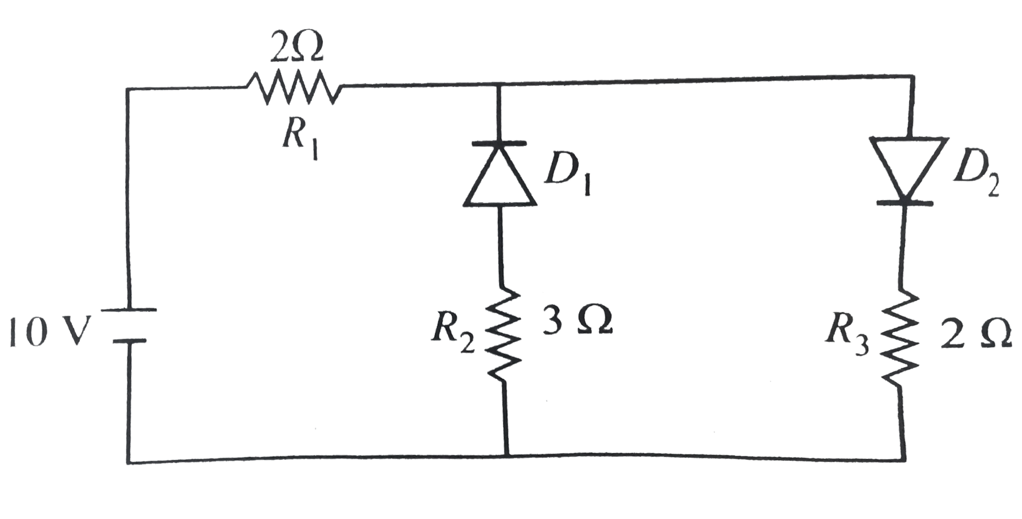
The given circuit has two ideal diodes connected as show in the figure. The current flowing through the resistance will be
A
2.5 A
B
10.0 A
C
1.43 A
D
3.13 A
Video Solution
Text Solution
The correct Answer is:A
|
Answer
Step by step video & image solution for The given circuit has two ideal diodes connected as show in the figure. The current flowing through the resistance R_(1) will be by Physics experts to help you in doubts & scoring excellent marks in Class 12 exams.
Updated on:21/07/2023Topper's Solved these Questions
- ELECTRONICS - SEMI CONDUCTORBOOK - MOTIONCHAPTER - ELECTRONICS - SEMI CONDUCTOREXERCISE - EXERCISE - 3
29 Videos
- ELECTRONICS - SEMI CONDUCTORBOOK - MOTIONCHAPTER - ELECTRONICS - SEMI CONDUCTOREXERCISE - EXERCISE - 1
41 Videos
- ELECTROMAGNETISMBOOK - MOTIONCHAPTER - ELECTROMAGNETISMEXERCISE - Exercise
136 Videos
- ELECTROSTATICSBOOK - MOTIONCHAPTER - ELECTROSTATICSEXERCISE - Exercise -3 Section (B) Previous Year Problems | JEE Main
30 Videos
Similar Questions
Knowledge Check
The given circuit has two ideal diodes connected as show in the figure. The current flowing through the resistance R1 will be
 A2.5 AB10.0 AC1.43 AD3.13 A
The given circuit has two ideal diodes connected as show in the figure. The current flowing through the resistance R1 will be
 A1.43AB3.13AC2.5AD10.0A
In the circuit, the current flowing through 10Ω resistance is
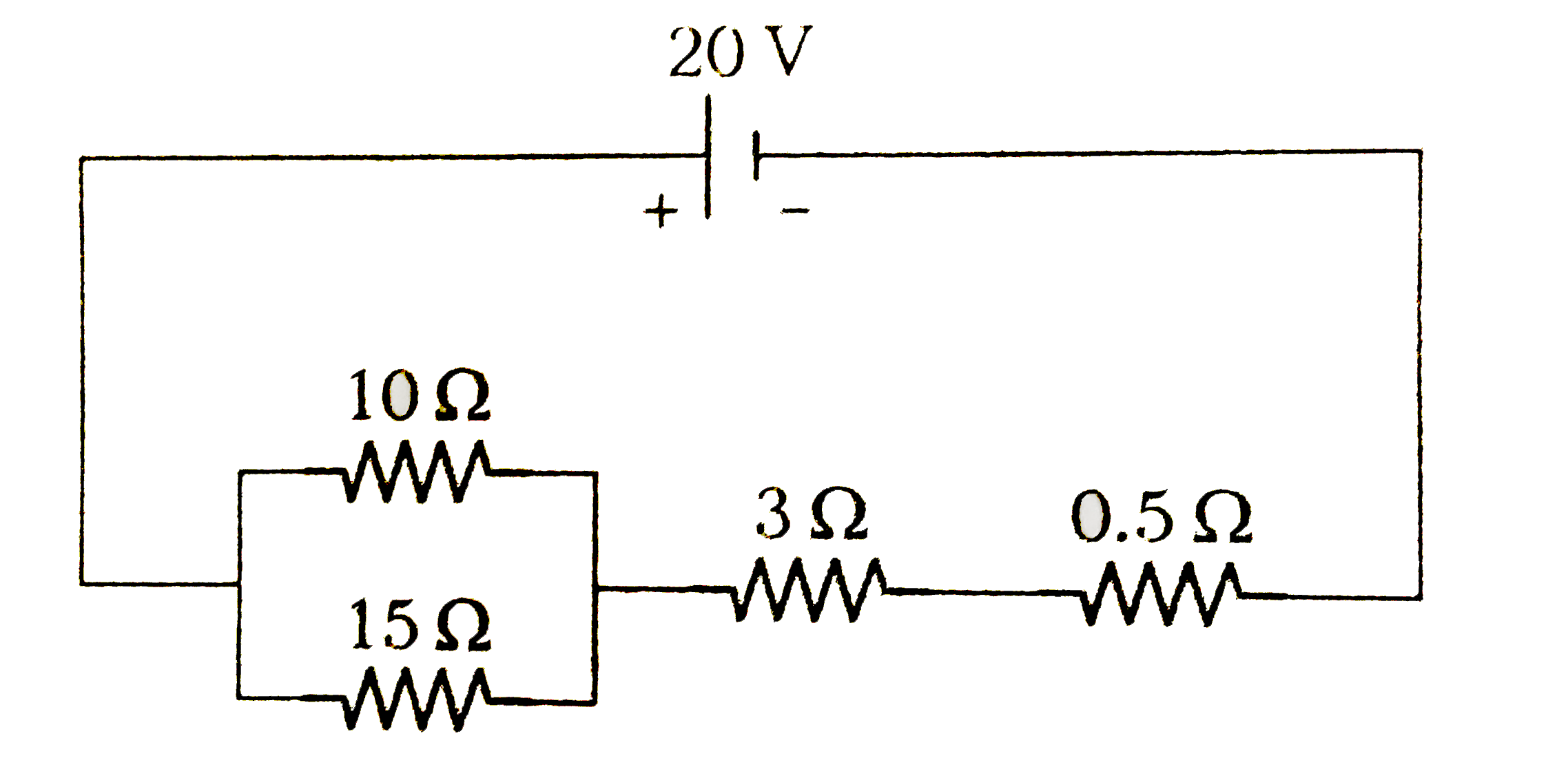 A12AB1.2AC0.8AD0.4A
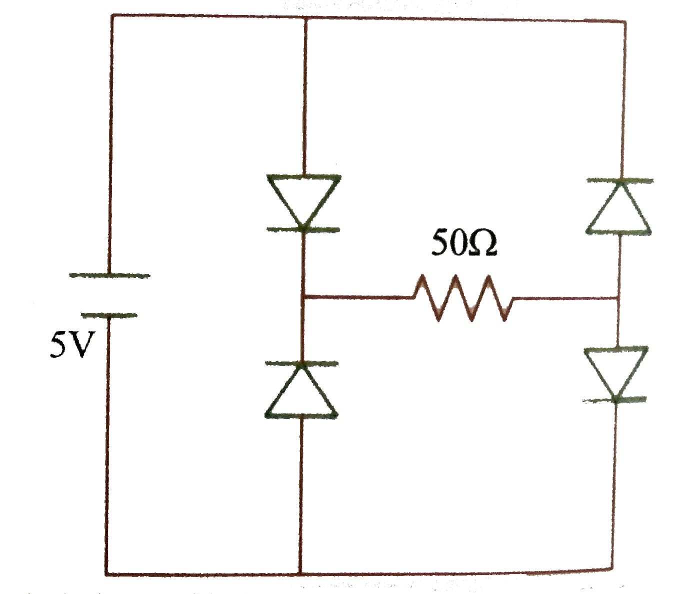
4 ideal diodes are connected as shown in the circuit the current through 50Ω is.
 .
.
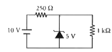
View SolutionIn the circuit, the current flowing through the zener diode is
View SolutionThe current through the ideal diode as shown in the figure is

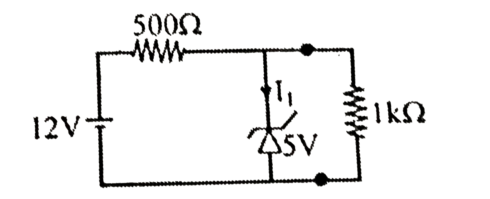
View SolutionThe current flowing through the zener diode in figure is -
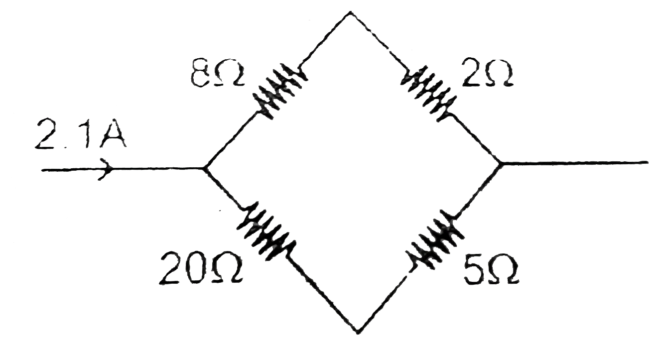
View SolutionIn the circuit in figure, the current flowing 5Ω resistance is :
View Solution

