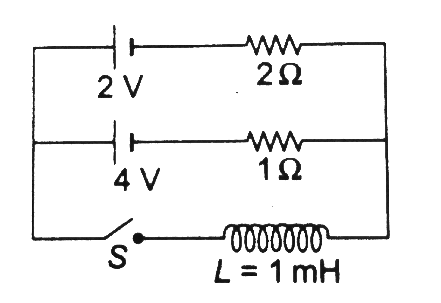
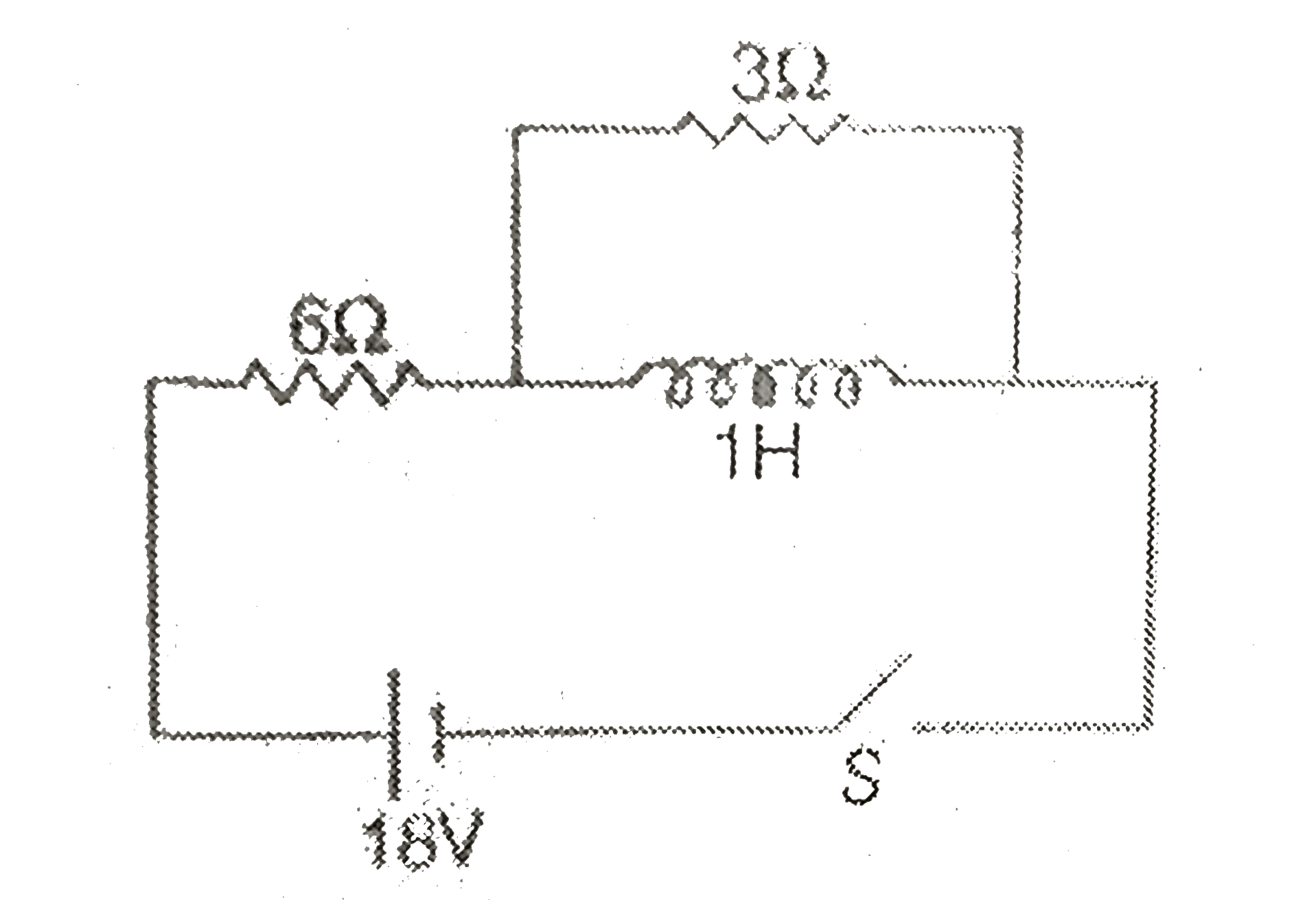
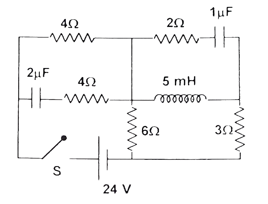
In the circuit shown in figure switch S is closed at time t=0
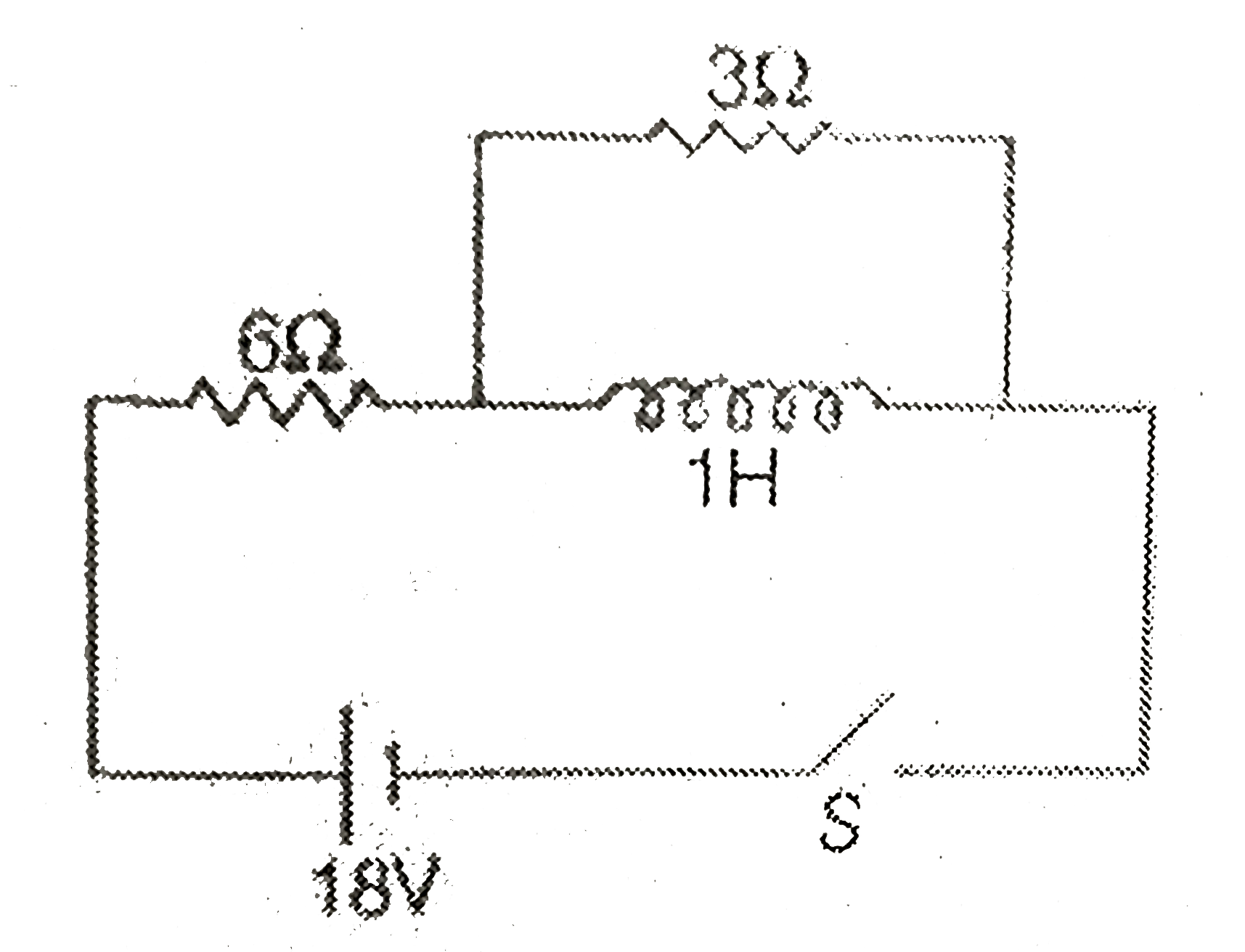
Takin left to right current through the indcutor as apositive current, current through inductor varies with time as
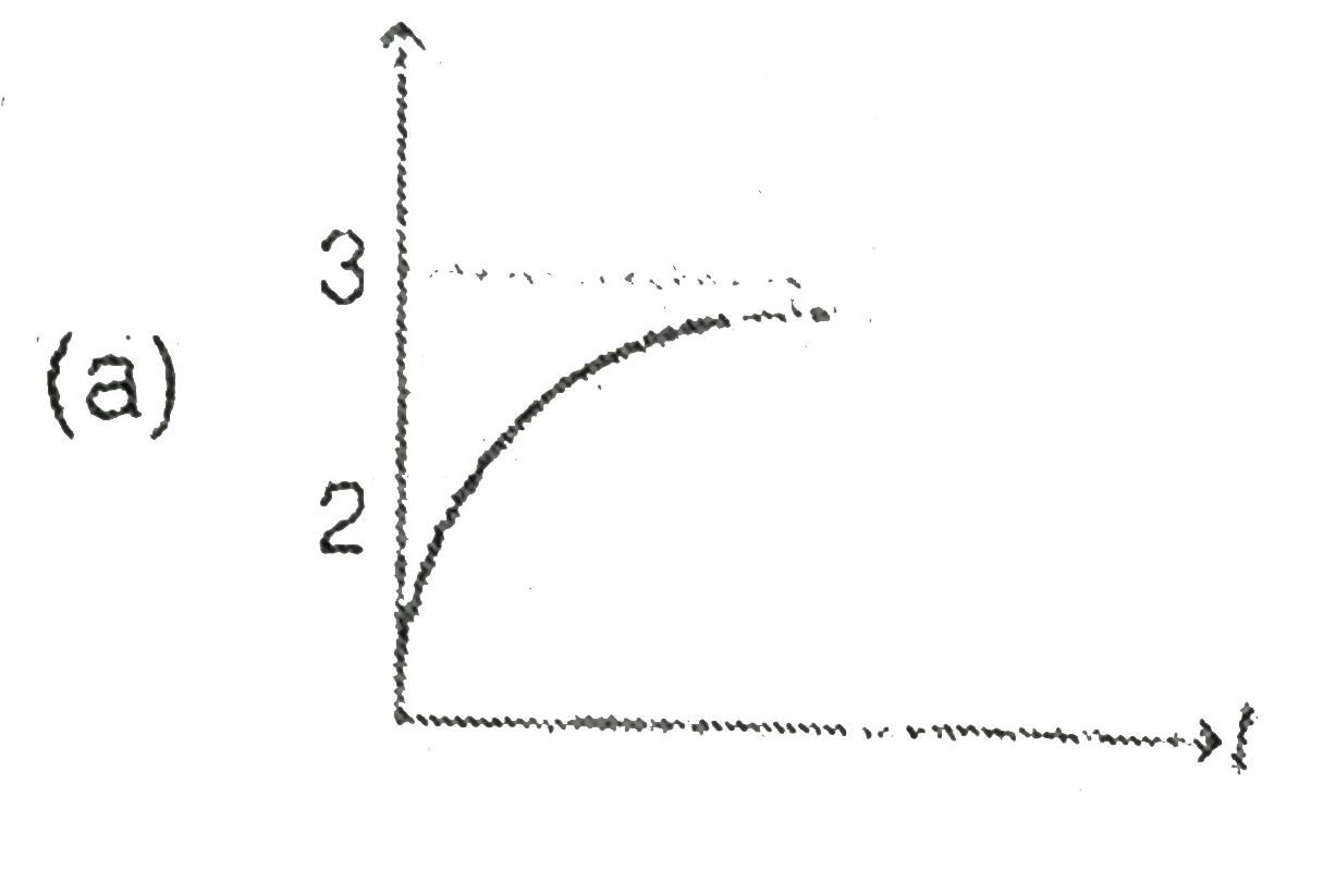
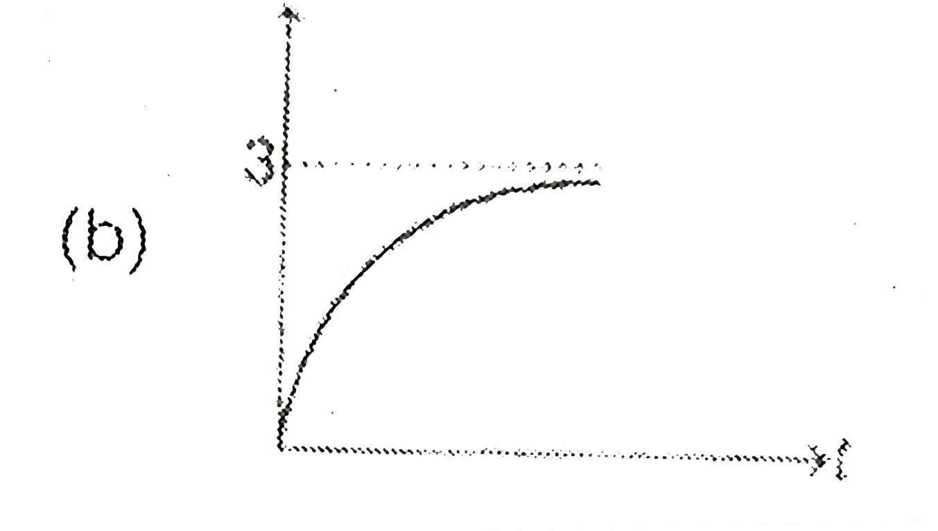
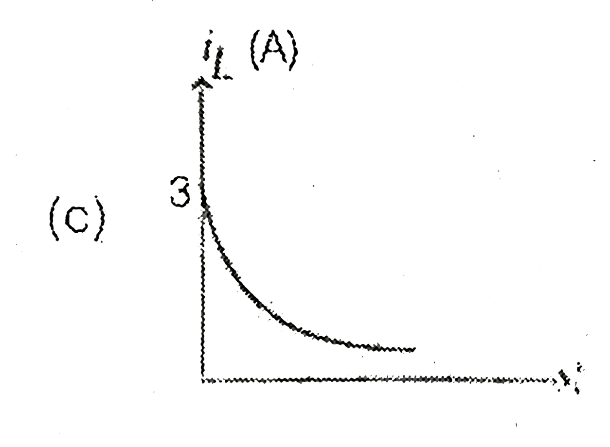
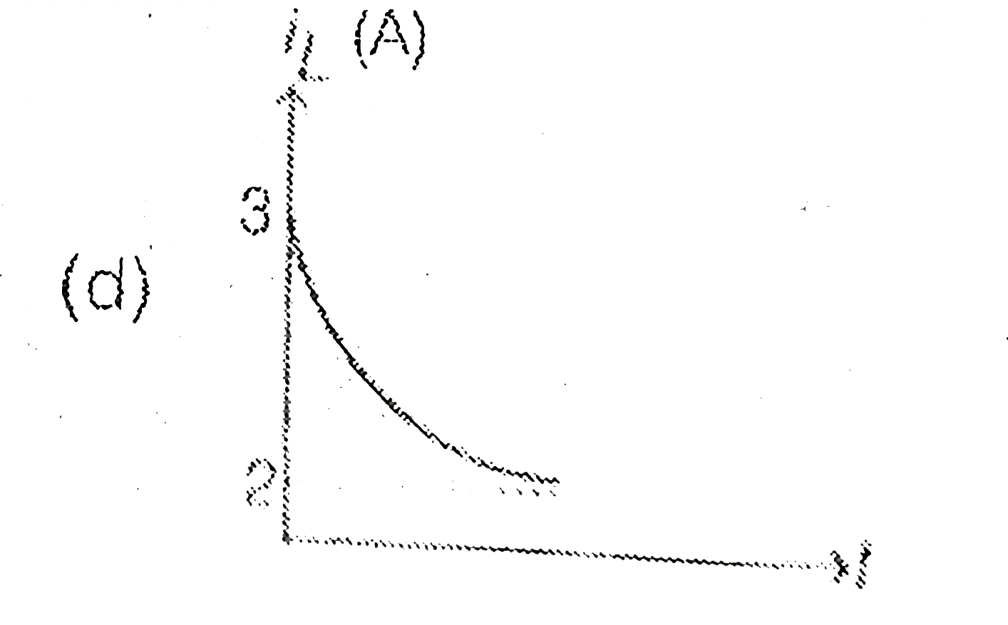
The correct Answer is:B
Step by step video, text & image solution for In the circuit shown in figure switch S is closed at time t=0 Takin left to right current through the indcutor as apositive current, current through inductor varies with time as by Physics experts to help you in doubts & scoring excellent marks in Class 12 exams.
Similar Questions
Knowledge Check
- Question 1 - Select One
In the circuit shown in figure switch S is closed at time t=0
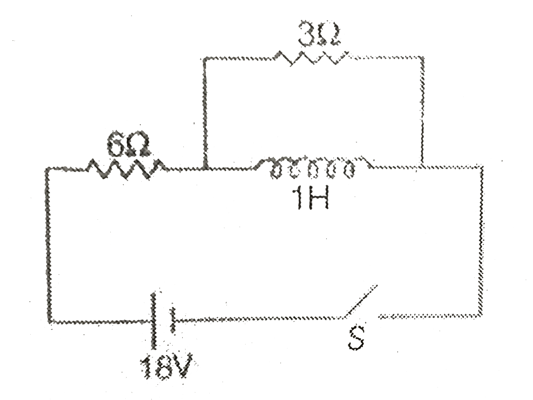
At what time current through 3Ω resistance and 1H inductor are equal?AIn√53BIn(83)CIn(53)DIn√83 - Question 2 - Select One
In the circuit shown in figure switch S is closed at time t=0. The charge which passes through the battery in one time constant is
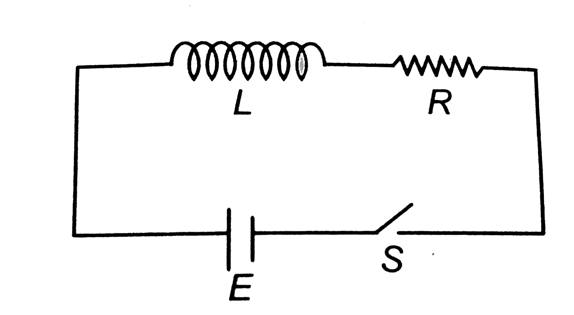 AeR2ELBE(LR)CELeR2DeLER
 - Question 3 - Select One
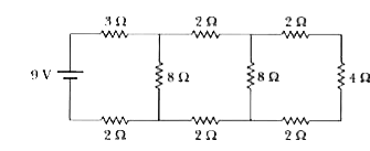
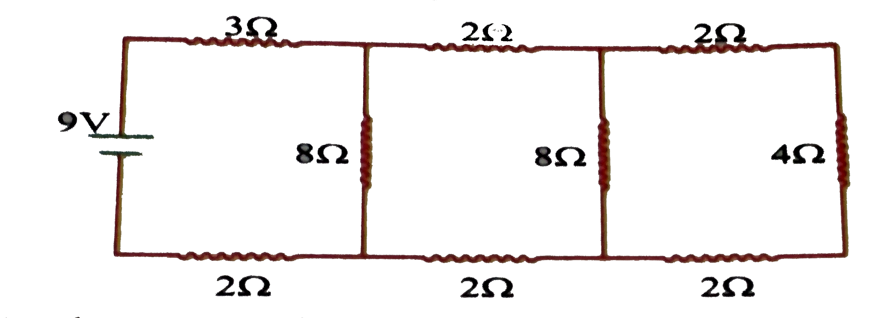
In the circuit shown in figure the current through
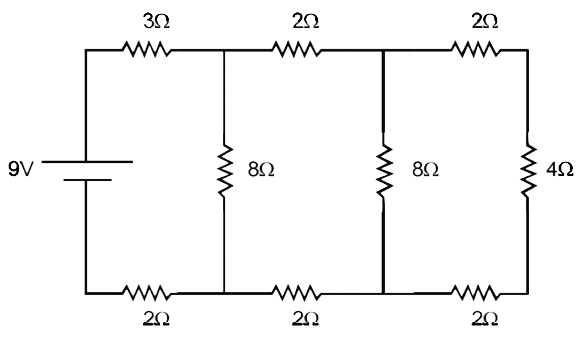 Athe 3Ω resistor is 0.50 A.Bthe 3Ω resistor is 0.25ACthe 4Ω is 0.50ADthe 4Ω resistor is 0.25A.
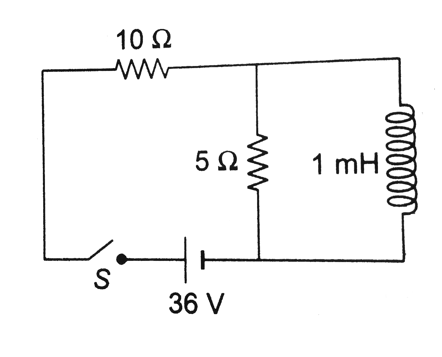
In the circuit arrangement shown in figure, the switch S is closed at t=0. Find the current in the inductance as a function of time? Does the current through 10Ω resistor vary with time or remains constant.
 View Solution
In the circuit shown in figure switch S is closed at time t=0
Current I from the battery at time t is given byView SolutionIn the circuit shown in the figure, the current through
 View Solution
In the circuit shown in the figure, the current throughView SolutionIn the circuit shown, the switch 'S' is closed at t=0. Then the current through the battery steady state reached is
 View Solution


