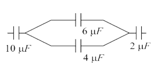
In the figure shown below, the charge on the left plate of the 10μF capacitor is −30μF. The change on the right plate of the 6μF capacitor is:
A
+18μC
B
−18μC
C
−12μC
D
+12μC
Video Solution
Text Solution
The correct Answer is:A
By division of charge on capacitor in parallel,
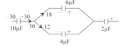 . q=+18μC.
|
Similar Questions
Knowledge Check
If charge on left plane of the 5μF capacitor in the circuit segment shiwn in the figure is −20μC, the charge on the right plate fo 3μF capacitor is
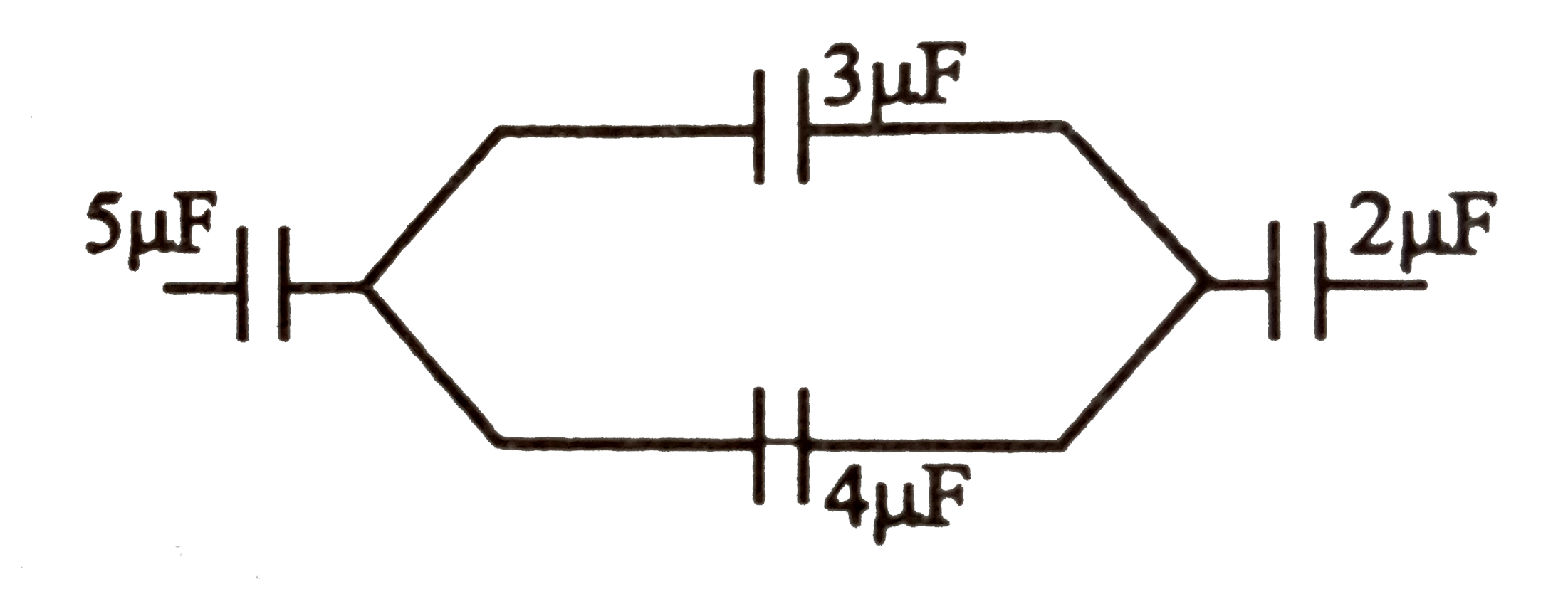 A+8.57μCB−8.57μCC+11.42μCD−11.42μC
In the given circuit, a charge of +80μC is given to the upper plate of the 4μF capacitor. Then in the steady state, the charge on the upper plate of the 3μF capacitor is
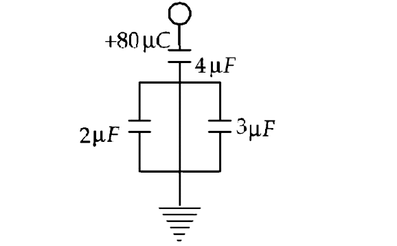 A(a) +32μCB(b) +40μCC(c) 48μCD(d) +80μC
In the circuit shown in figure, the ratio of charges on 5μFand4μF capacitor is :
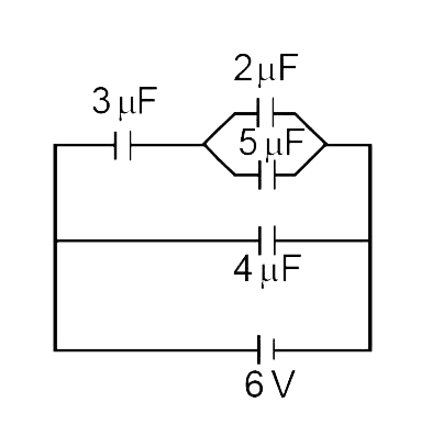 A4/5B3/5C3/8D1/2
In figure (below) the charge on the 1.5μF capacitor is
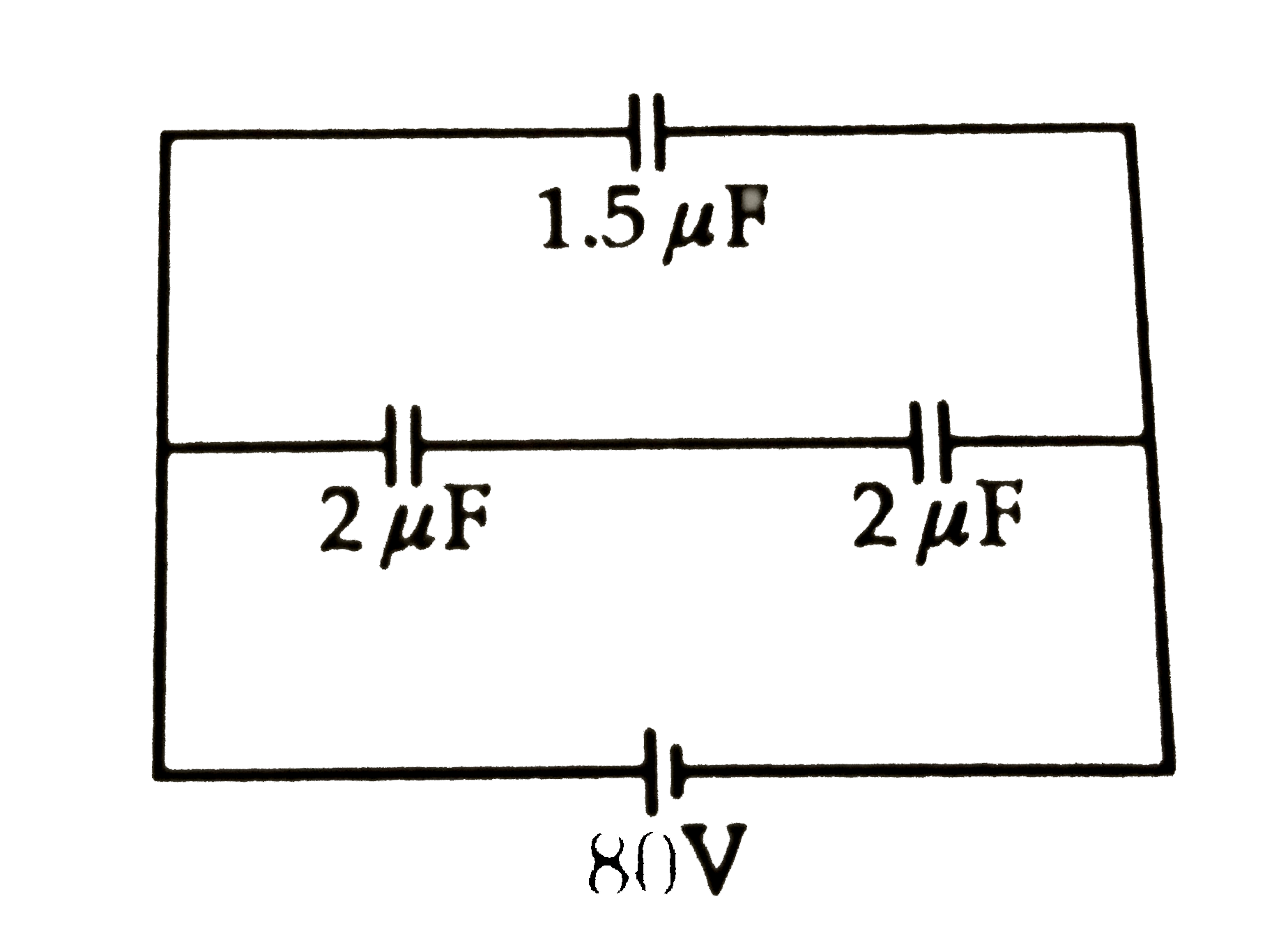
View SolutionIn the circuit shown in the figure, in steady state:

The charge on 5μF capacitor is
View SolutionIn the circuit shown in figure, the ratio of charge on 5μF and 2μF capacitor is
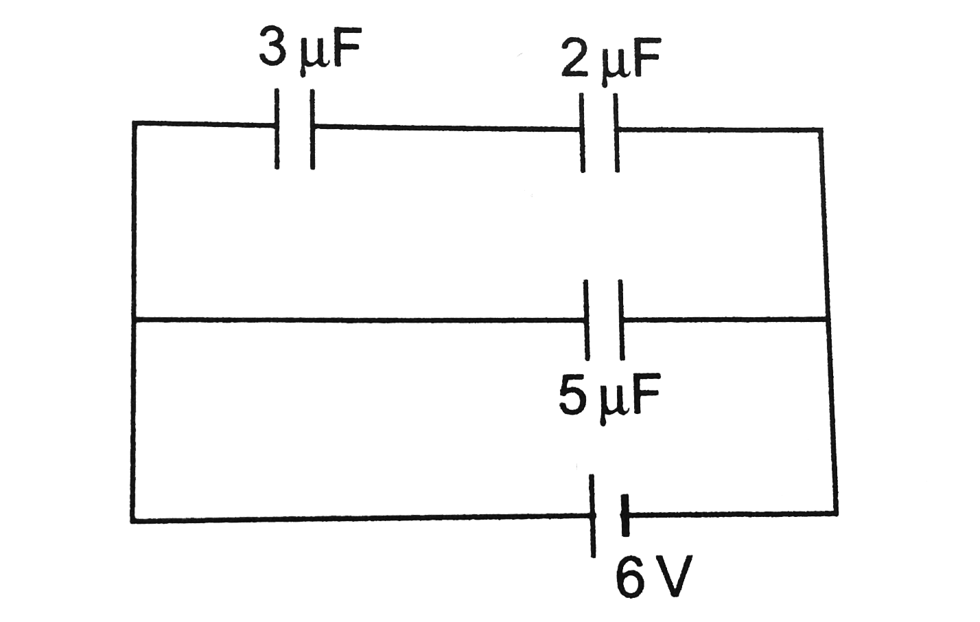
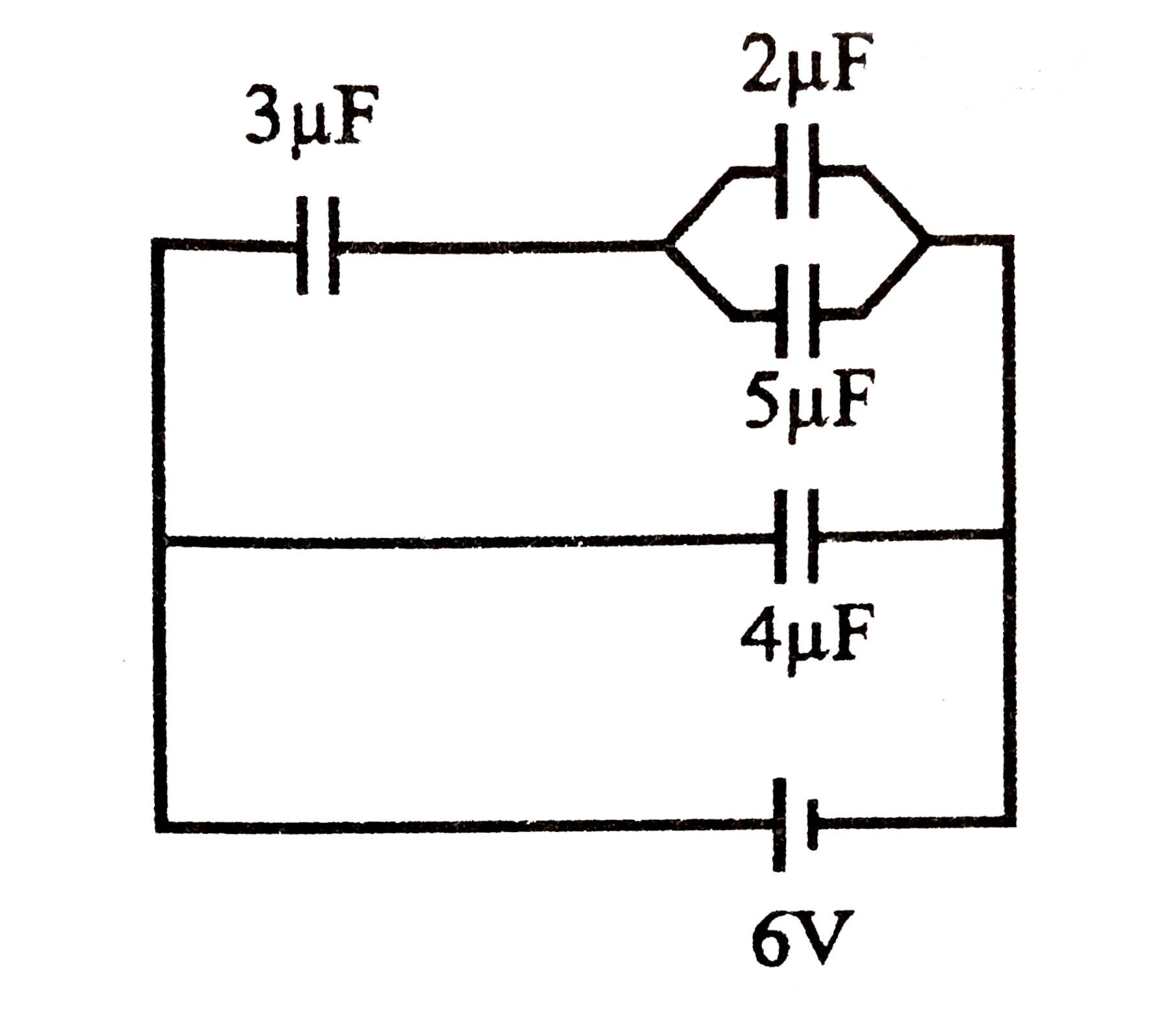
View SolutionIn the circuit shown in figure, the ration of charged on 5μF and 4μF capacitor is-
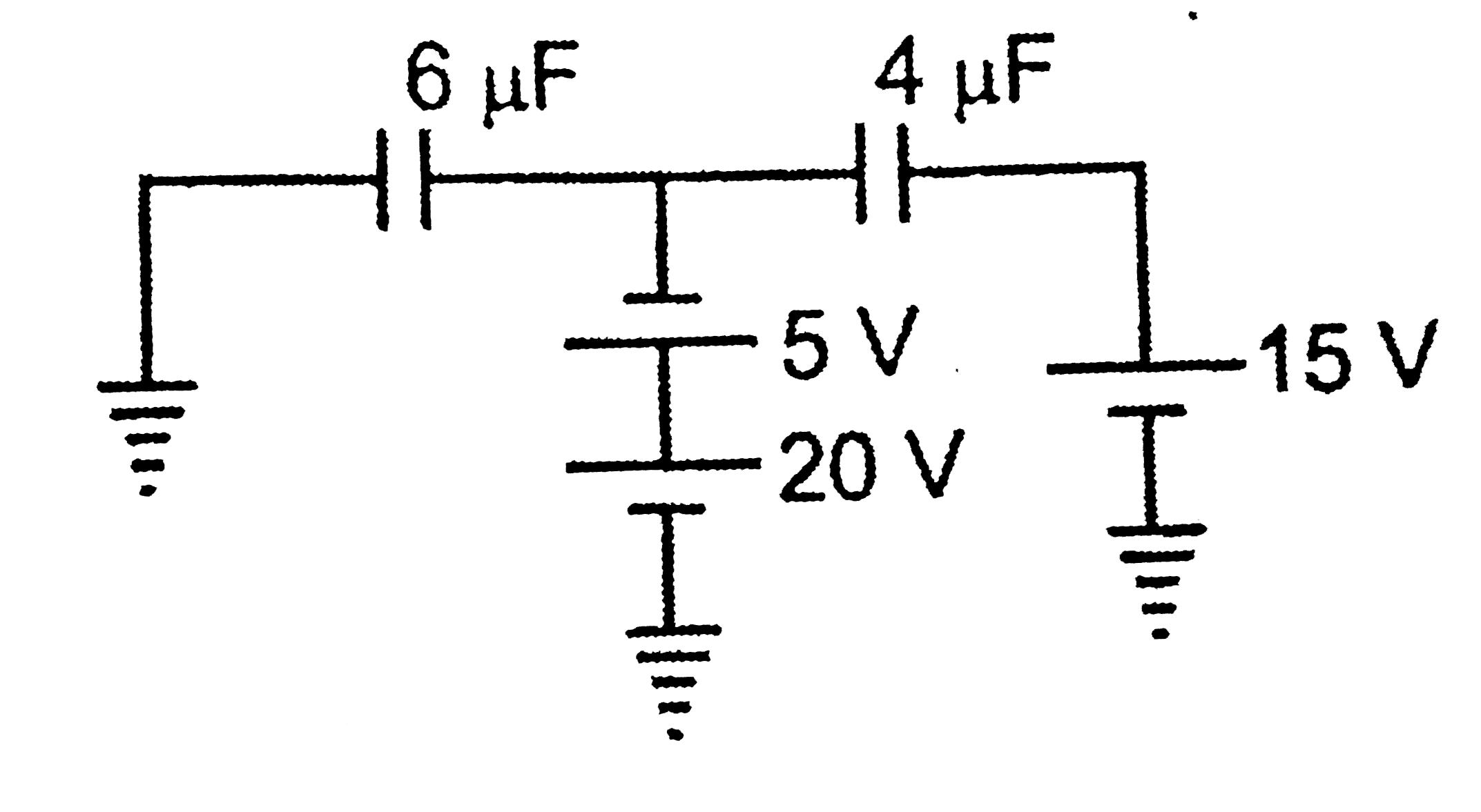
View SolutionFor the arrangement shown in the figure, the charge on the 4μF capacitor is
View Solution


