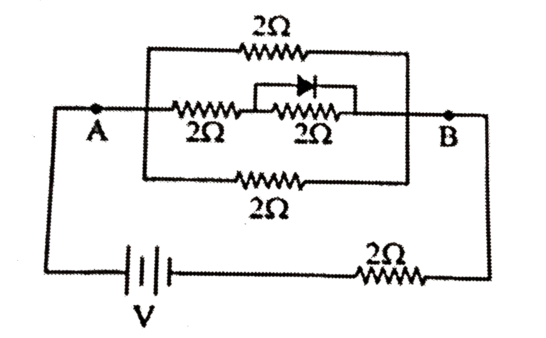
In the circuit shown in figure , the diode is ideal The potential difference between A and B is
A
V/4
B
V
C
zero
D
V/2
Video Solution
Text Solution
The correct Answer is:1
Diode is FB
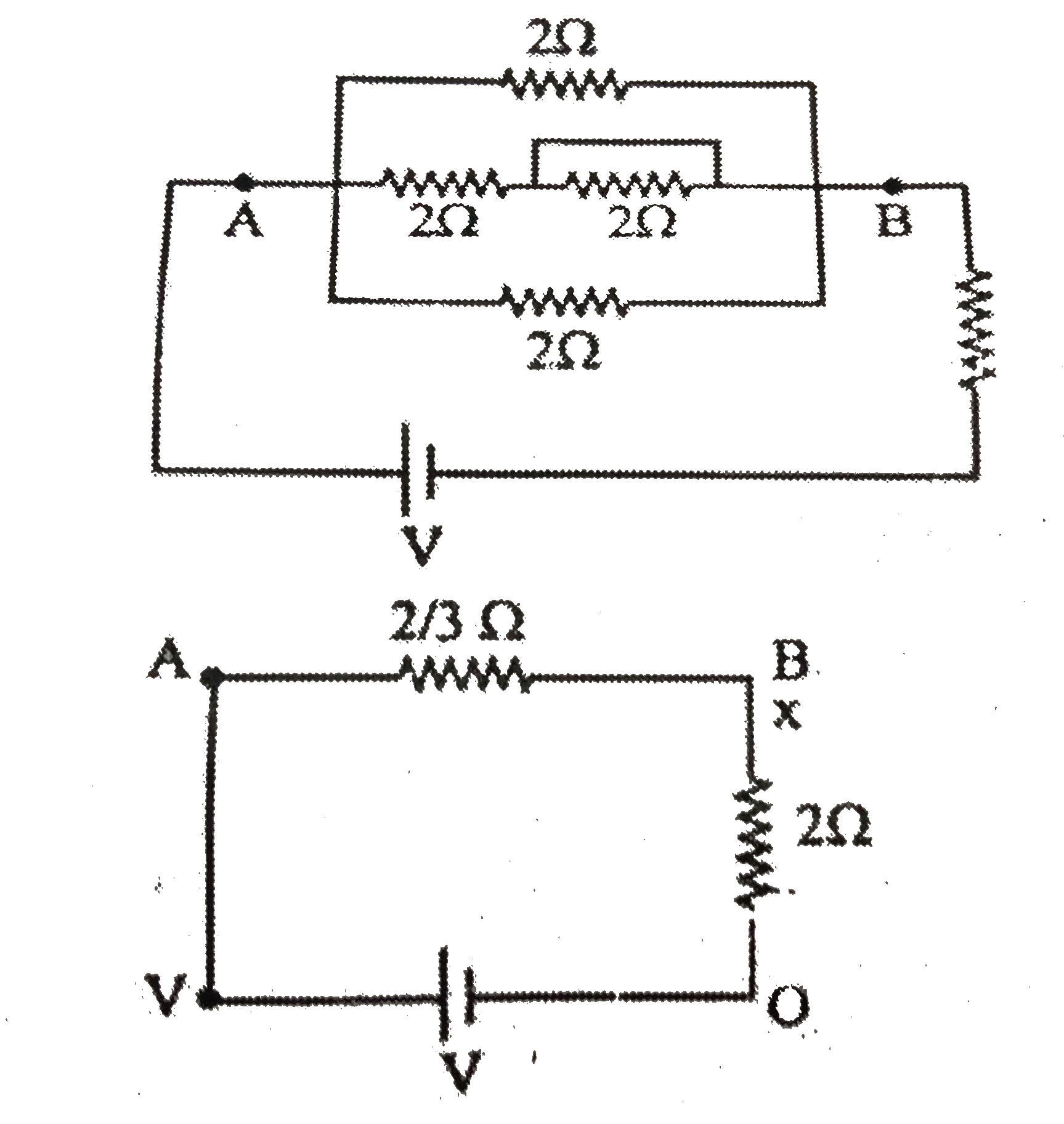
x−v23+x−02=0
⇒3x−3v+x=0
x=3V4
VA−VB=V−3V4
=V4
|
Topper's Solved these Questions
Similar Questions
Knowledge Check
In the diode circuit shown in figure,
 AD1andD2 are reverse biasedBD1andD2 are forward biasedCD1 is forward biased and D2 is reverse biased.DD1 is reverse biased and D2 is forward biased.
The potential difference between A and B as shown in figure is
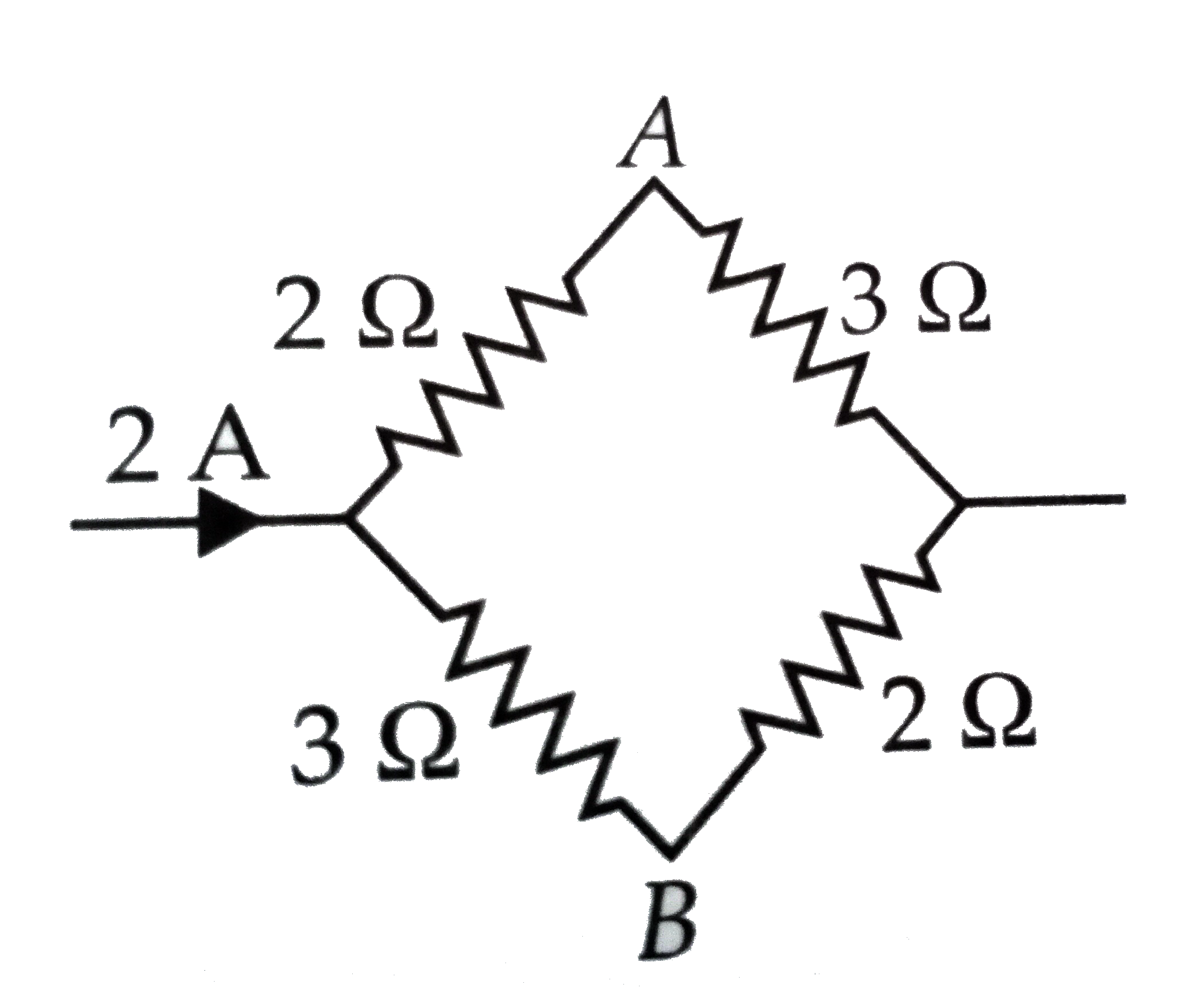 A1VB2VC3VD4V
In the given circuit, the potential difference between A and B is
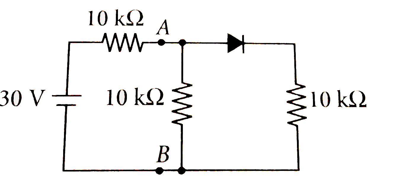 A10 VB15 VC20 VD5V
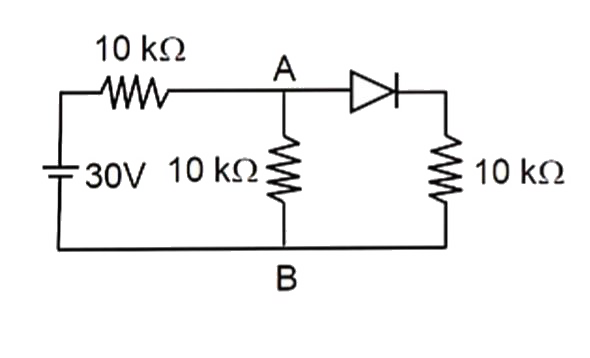
Find the potential difference between A and B as shown in the figure
View SolutionIn the circuit shown, the potential differnet between A and B is .
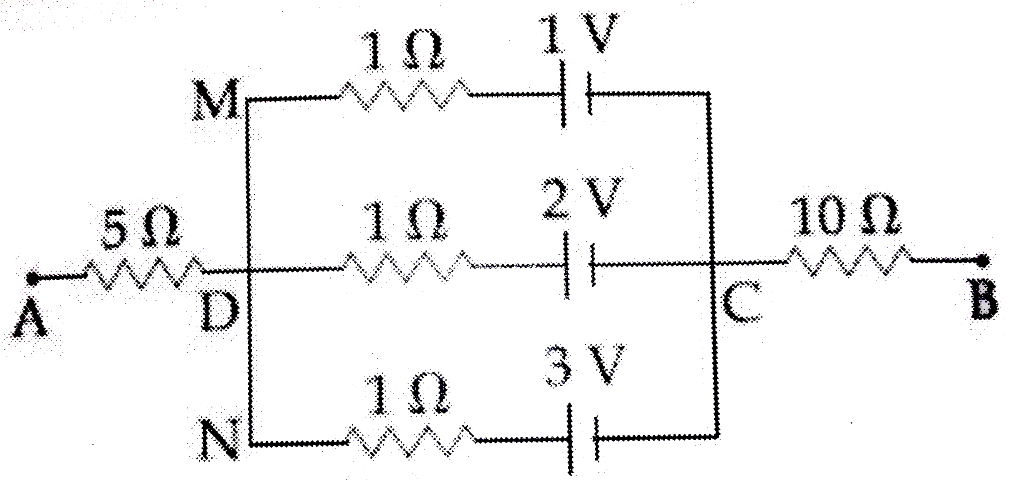
View SolutionIn the network shown in the figure, the potential difference between A and B is :
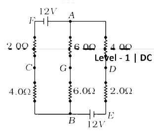
View SolutionIn the circuit shown in figure -3.113 Find potential difference between the point A and B and the currents though each branch.

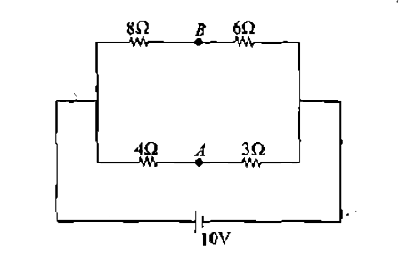
View SolutionIn the circuit shown in figure-3.331, the potential difference between points A and Bis :
View Solution

