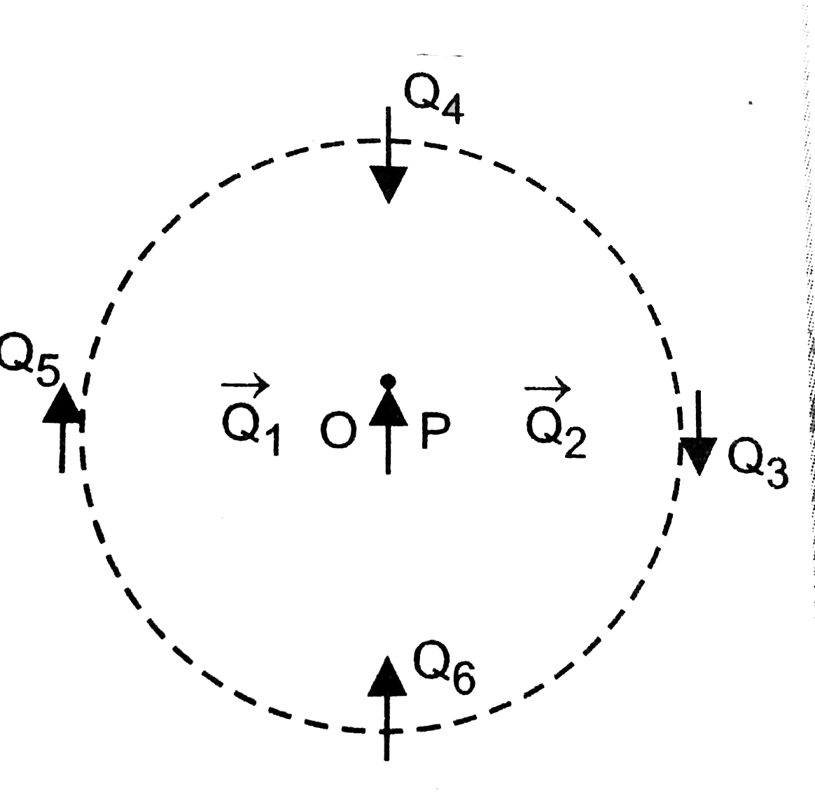
Figure shows a small magnetised needle P placed at a point O. The arrow shows the direction of magnetic moment. The other arrows show different positions (and orientations of the magnetic moment) of another identical magnetised needle Q.

(a) In which configuration is the system not in equilibrium?
(b) In which configuration is the system in (i) stable and (ii) unstable equilibrium?
(c) Which configuration corresponds to the lowest potential energy among all the configurations shown?
Potential energy is minimum when angle between M and B is 0∘, i.e. U=MB Example : AB6.
Topper's Solved these Questions
- UNIT–III & UNIT–IV MAGNETIC EFFECTS OF CURRENT AND MAGNETISM & E.M.I. AND ALTERNATING CURRENTBOOK - CBSE COMPLEMENTARY MATERIALCHAPTER - UNIT–III & UNIT–IV MAGNETIC EFFECTS OF CURRENT AND MAGNETISM & E.M.I. AND ALTERNATING CURRENTEXERCISE - LONG ANSWER QUESTIONS (5 Marks)
5 Videos
- SAMPLE QUESTION PAPER 2019BOOK - CBSE COMPLEMENTARY MATERIALCHAPTER - SAMPLE QUESTION PAPER 2019EXERCISE - Section C
19 Videos
Similar Questions
Figure shows a small magnetised needle P placed at a point O. The arrow shows the direction of magnetic moment. The other arrows show different positions (and orientations of the magnetic moment) of another identical magnetised needle Q.

(a) In which configuration is the system not in equilibrium?
(b) In which configuration is the system in (i) stable and (ii) unstable equilibrium?
(c) Which configuration corresponds to the lowest potential energy among all the configurations shown?
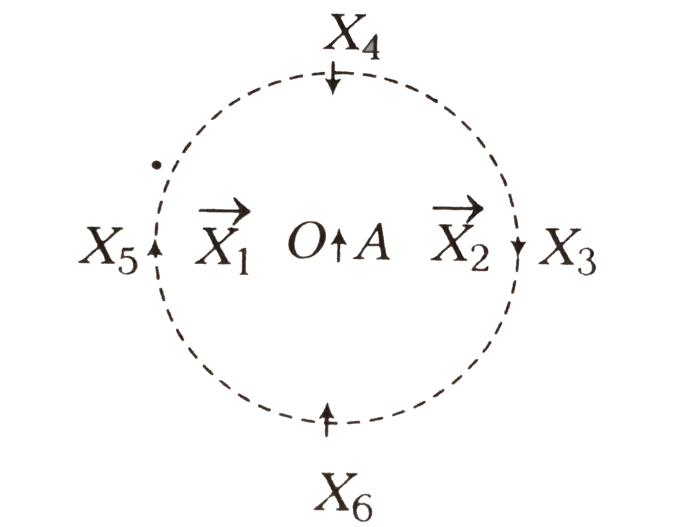
View SolutionConsider the situation shown in the diagram, where A small magnetised needle A is placed at a centre marked, as O. The direction of its mangetic moment I s indicated by arrow. The other arrow show different position (and orientations of the magnetic moment) of antoher identical magnetised eedle X.
In which configuration the system is not in equlibrium?
(ii) In which configuration is the system in (a) stable and (b) unsable equilibrium
(iii) Which configuration corresponds to the lowest potentials energy among all the configuration shown

View Solution
Knowledge Check
The lowest magnetic moment is shown by the transition metal ion with the configuration
A3d7B3d9C3d2D3d3In transistor symbols, the arrows shows shows the direction of-
Acurrent in the emitterBelectron current in the emitterCholes current in the emitterDNone of theseWhich one of the following shows highest magnetic moment?
AV3+BCr3+CFe3+DCo3+
Figure shows a small magnetised needle P placed at a point O. The arrow shows the direction of magnetic moment. The other arrows show different positions (and orientations of the magnetic moment) of another identical magnetised needle Q.

(a) In which configuration is the system not in equilibrium?
(b) In which configuration is the system in (i) stable and (ii) unstable equilibrium?
(c) Which configuration corresponds to the lowest potential energy among all the configurations shown?
View SolutionFigure shows a small magnetised needle P placed at a point O. The arrow shows the direction of magnetic moment. The other arrows show different positions (and orientations of the magnetic moment) of another identical magnetised needle Q.

(a) In which configuration is the system not in equilibrium?
(b) In which configuration is the system in (i) stable and (ii) unstable equilibrium?
(c) Which configuration corresponds to the lowest potential energy among all the configurations shown?
View SolutionIn which orientation, a dipole placed in a uniform electric field is in (i) stable (ii) unstable equilibrium ?
View SolutionSome metals get magnetised by orientation of atomic magnetic moments in external magnetic field. What are they called?
View SolutionFind electronic configuration and magnetic moment of Gd3+
View Solution
