Draw a circuit diagram showing the biasing of a photodiode.
Step-by-Step Solution:
1. Understand the Photodiode Structure:
- A photodiode is a semiconductor device that consists of a p-n junction. The p-side is doped with acceptor impurities, while the n-side is doped with donor impurities.
2. Identify the Circuit Components:
- The circuit will include:
- A photodiode (represented by its symbol).
- A power supply (battery).
- A resistor (to limit current).
- An ammeter (to measure the current flowing through the circuit).
3. Draw the Photodiode Symbol:
- The symbol for a photodiode is similar to that of a p-n junction diode, but it may include arrows indicating the direction of light incidence.
4. Connect the Photodiode in Reverse Bias:
- Connect the p-side of the photodiode to the negative terminal of the battery.
- Connect the n-side of the photodiode to the positive terminal of the battery. This configuration is known as reverse biasing.
5. Add the Resistor and Ammeter:
- Place a resistor in series with the photodiode to limit the current.
- Connect an ammeter in series to measure the current generated when light is incident on the photodiode.
6. Label the Circuit Components:
- Clearly label the photodiode, battery, resistor, and ammeter in the circuit diagram for clarity.
7. Final Touches:
- Ensure the circuit diagram is neat and all connections are clearly shown.
Circuit Diagram:
+⊢−−−−|>o−−−−|R⊢−−A−−−−|−|Pho→diode|||∣||||BaeryAmmeter|
- A photodiode is a semiconductor device that consists of a p-n junction. The p-side is doped with acceptor impurities, while the n-side is doped with donor impurities.
- The circuit will include:
- A photodiode (represented by its symbol).
- A power supply (battery).
- A resistor (to limit current).
- An ammeter (to measure the current flowing through the circuit).
- The symbol for a photodiode is similar to that of a p-n junction diode, but it may include arrows indicating the direction of light incidence.
- Connect the p-side of the photodiode to the negative terminal of the battery.
- Connect the n-side of the photodiode to the positive terminal of the battery. This configuration is known as reverse biasing.
- Place a resistor in series with the photodiode to limit the current.
- Connect an ammeter in series to measure the current generated when light is incident on the photodiode.
- Clearly label the photodiode, battery, resistor, and ammeter in the circuit diagram for clarity.
- Ensure the circuit diagram is neat and all connections are clearly shown.
+⊢−−−−|>o−−−−|R⊢−−A−−−−|−|Pho→diode|||∣||||BaeryAmmeter|
Topper's Solved these Questions
- BOOK - CBSE COMPLEMENTARY MATERIALCHAPTER - ELECTRONIC DEVICES EXERCISE - SHORT ANSWER QUESTIONS (2 MARKS)13videos
ELECTRONIC DEVICES
- BOOK - CBSE COMPLEMENTARY MATERIALCHAPTER - ELECTRONIC DEVICES EXERCISE - SHORT ANSWER QUESTIONS (3 MARKS)7videos
ELECTRONIC DEVICES
- BOOK - CBSE COMPLEMENTARY MATERIALCHAPTER - ELECTROMAGNETIC WAVES AND OPTICSEXERCISE - 1 mark question11videos
ELECTROMAGNETIC WAVES AND OPTICS
- BOOK - CBSE COMPLEMENTARY MATERIALCHAPTER - ELECTROSTATICS AND CURRENT ELECTRICITY EXERCISE - NUMERICALS49videos
ELECTROSTATICS AND CURRENT ELECTRICITY
Similar Questions
With the help of a neat circuit diagram, explain the working of a photodiode. State its any'two uses.
View SolutionDraw a circuit diagram to show biasing of a solar cell. Draw its characteristic curve and explain it
View SolutionDraw a circuit diagram to show biasing of a p-n-p transistor. Explain the transistor action.
View SolutionExplain with the help of a circuit diagram, the working of a photodiode. Write briefly how it is used to detect the optical signals.
View Solution(a) Draw a neat diagram showing forward biasing of a p-n junciton
Briefly explain its working draw it s V-I charcteristics for two different intensities of illuminationView SolutionDraw the circuit diagram of an illuminated photodiode in reverse bias? How is photodiode used to measure light intensity?
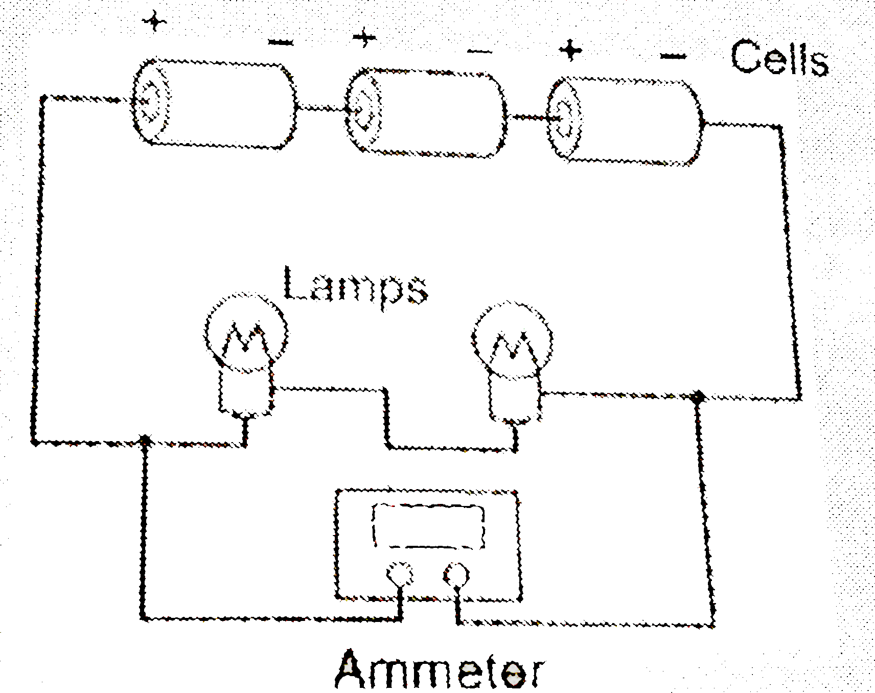
View SolutionA student made an electric circuit shown here to measure the current through two lamps.
(a) Are the lamps in series or parallel?
(b) The student has made a mistake in this circuit. What is the mistake? ,
(c) Draw a circuit diagram to show the correct way to connect the circuit. Use the proper circuit symbols in your diagram.
 View Solution
(a) Draw a circuit diagram showing two lamps, one cell and a switch connected in series.
(b) How can you change the brightness of the lamps?View SolutionWith the help of a diagram, show the biasing of a light emitting diode (LED). Give its two advantages over conventional incandescent lamps.
View SolutionWhat is the electromagnet? Draw a circuit diagram to show low a soft iron piece can be transformed into an electromagnet.
View Solution

