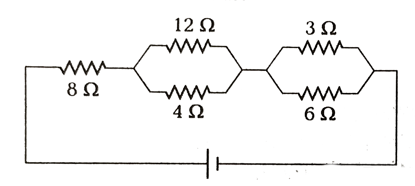
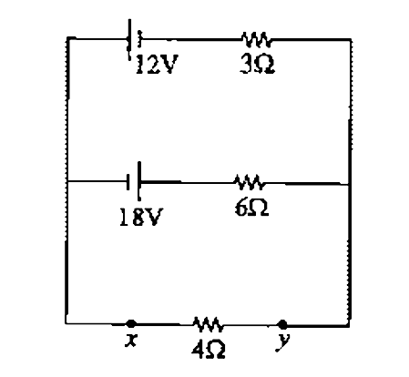
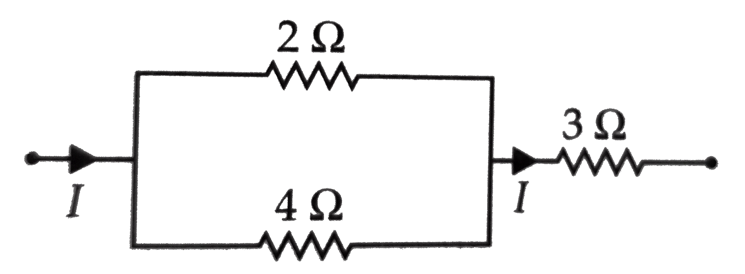
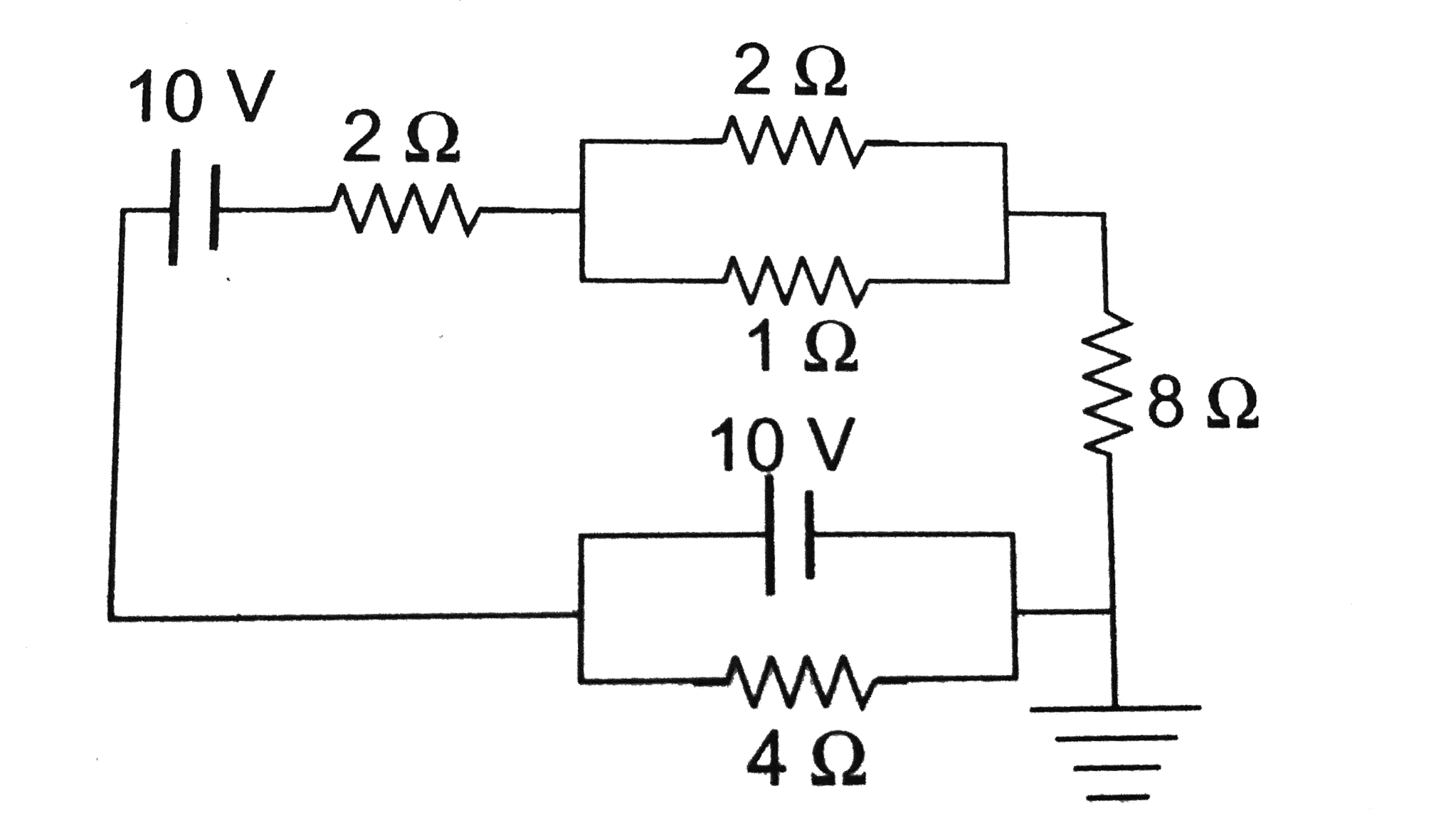
In the circuit shown in figure heat developed across resistances are in the ratio
A
B
C
D
Video Solution
Text Solution
The correct Answer is:D
Current through
Hence produced per second,
Current through,
Hence produced per second
Current through,
Heat produced,
|
Topper's Solved these Questions
- CURRENT ELECTRICITYBook:NCERT FINGERTIPSChapter:CURRENT ELECTRICITYExercise:Combination Of Resistors : Series And Parallel
Explore 22 Videos
- CURRENT ELECTRICITYBook:NCERT FINGERTIPSChapter:CURRENT ELECTRICITYExercise:Cells, Emf, Internal Resistance
Explore 6 Videos
- CURRENT ELECTRICITYBook:NCERT FINGERTIPSChapter:CURRENT ELECTRICITYExercise:Temperature Dependence Of Resistivity
Explore 7 Videos
- COMMUNITCATION SYSTEMSBook:NCERT FINGERTIPSChapter:COMMUNITCATION SYSTEMSExercise:HOTS
Explore 10 Videos
- DUAL NATURE OF RADIATION AND MATTER Book:NCERT FINGERTIPSChapter:DUAL NATURE OF RADIATION AND MATTER Exercise:Assertion And Reason
Explore 15 Videos
Similar Questions
Knowledge Check
In the circuit shown in figure, power developed across 1Ω,2Ω and 3Ω resistance are in the ratio of
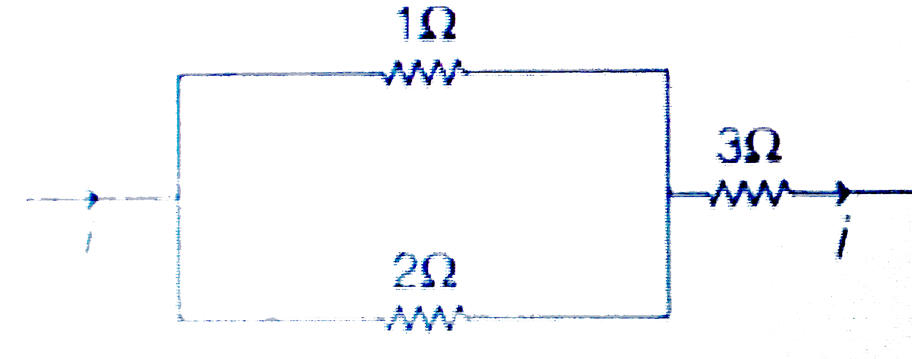 A1:2:3B4:2:27C6:4:9D2:1:27
In the circuit shown in the figure, the current flowing in 2Ω resistance
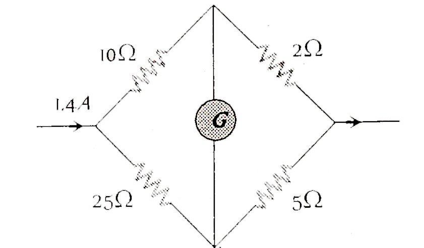 A1.4AB1.2AC0.4AD1.0A
In the circuit shown in the following figure, the heat product in the 5Ω resistance due to the current flowing it is 10 cal/s. The heat generated in 4Ω resistance and 6Ω resistor is
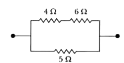 A1 cal/sB2 cal/sC3 cal/sD4 cal/s
In the circuit shown in figure, the equivalent resistance between and is __________ Ω.
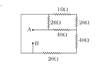
View SolutionIn the circuit shown, reading of the voltmeter connected across 400Ω resistance is 60 V. If it is connected across 300Ω resistance then reading in volt will be
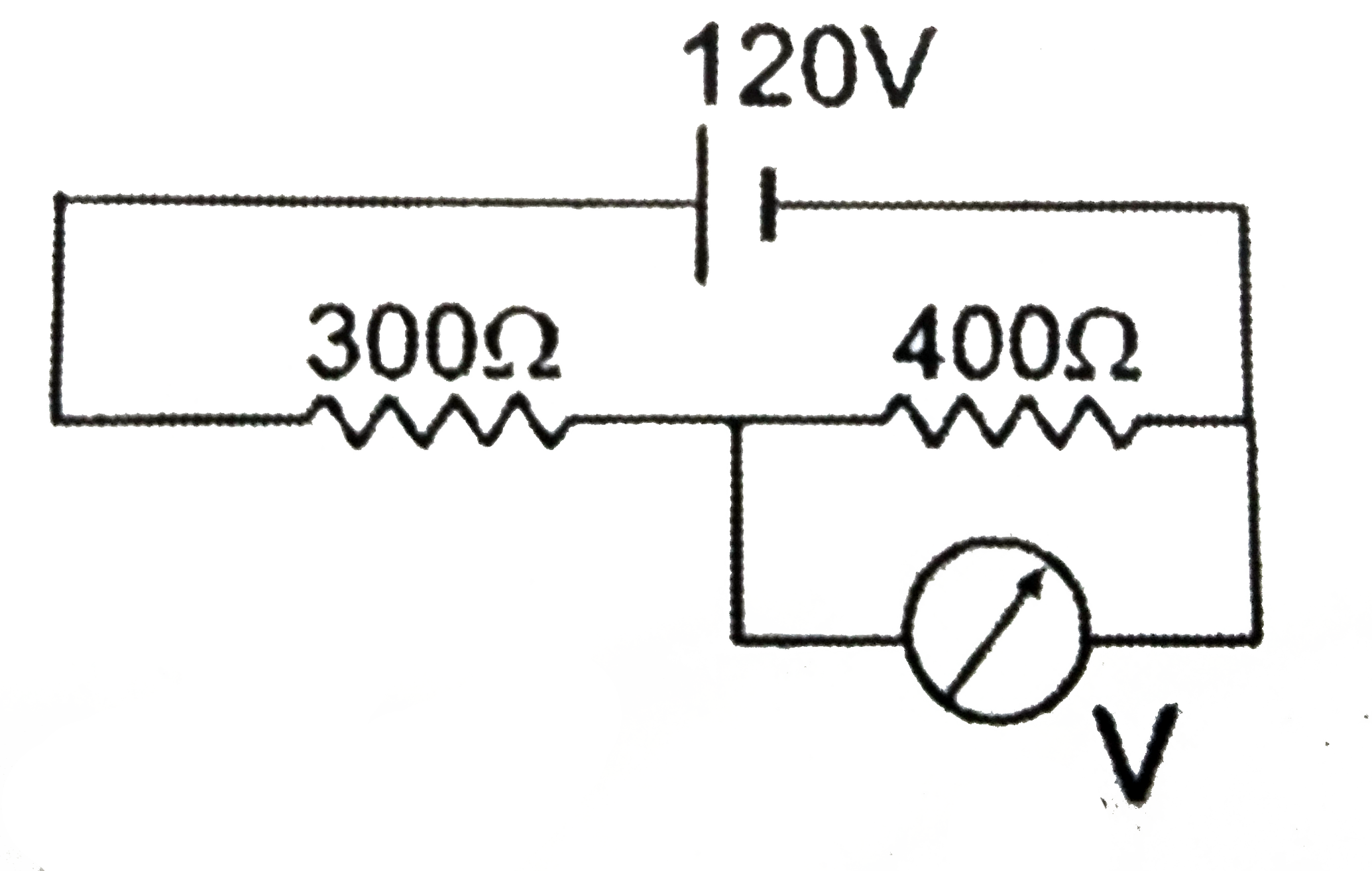
View SolutionIn the circuit shown the currents in 4Ω and 8Ω resistances are
View SolutionIn the circuit shown in figure switch S is closed at time t=0
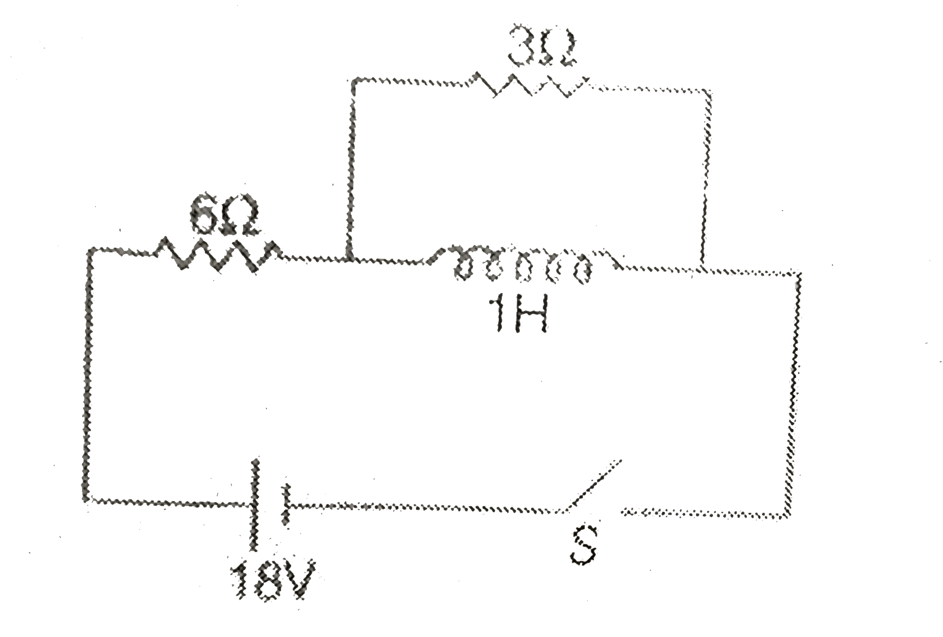
Potential difference across 3Ω resistance at time t is given by
View SolutionIn the circuit shown below:

The potential difference across the 3Ω resistor is:
View Solution
