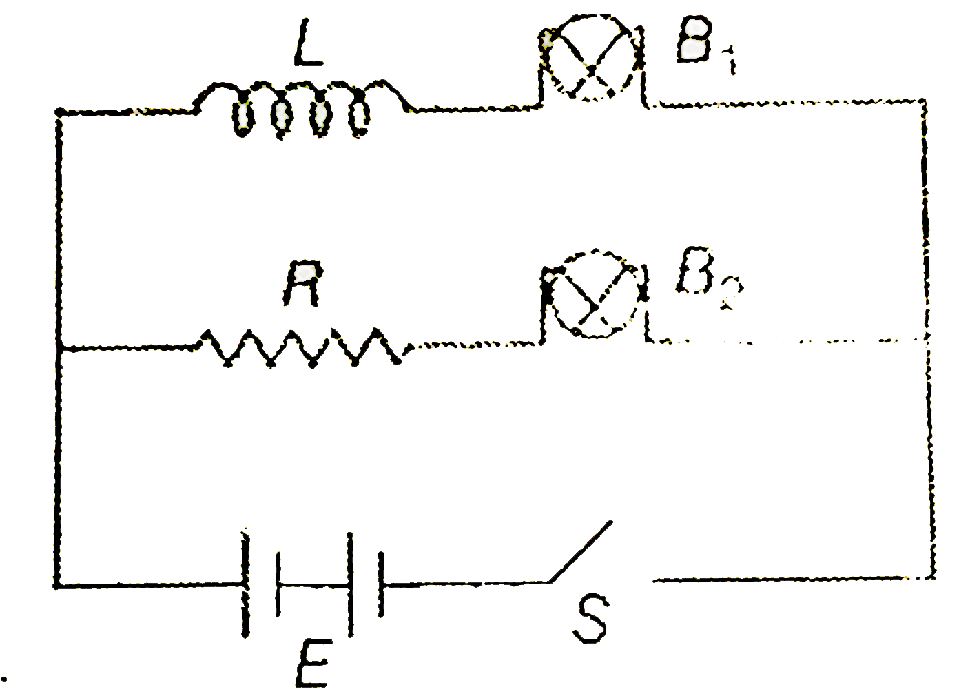
The adjoining figure shows two bulbs and resistor and an inductor and . When the switch is turned off
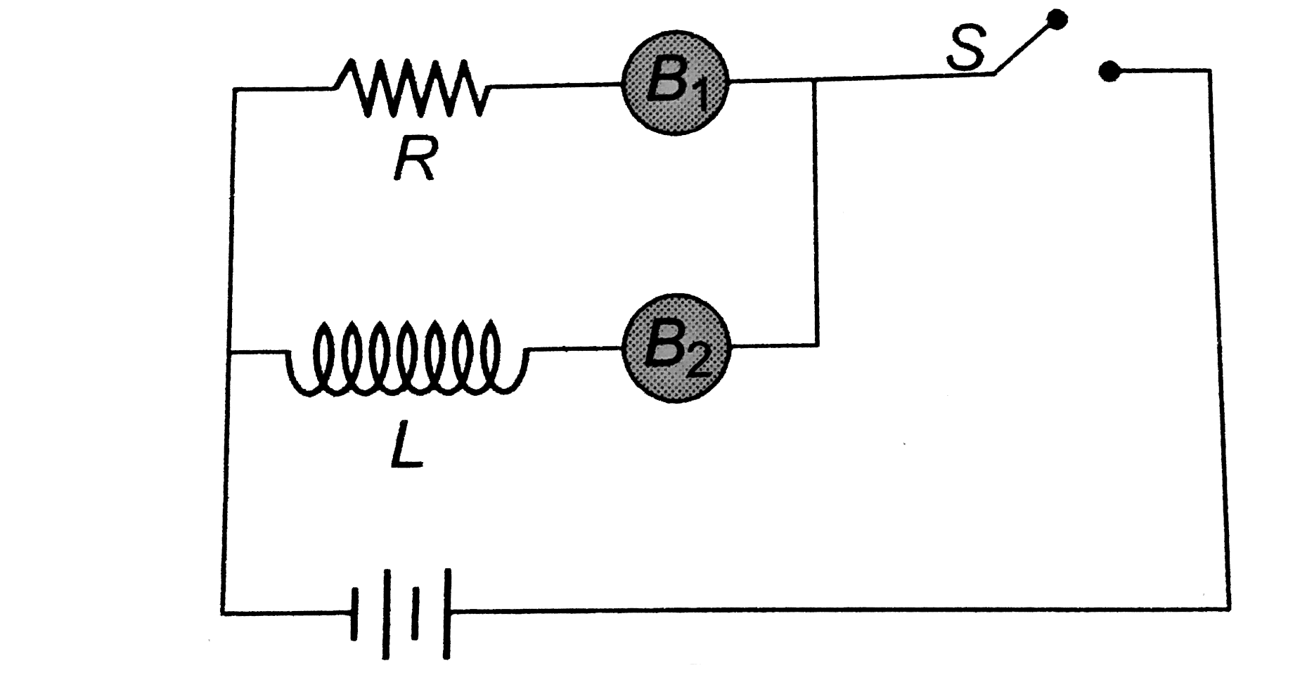
Both and die out promptly
Both and die out with some delay
dies out promptly but with some delay
dies out promptly but with some delay
The correct Answer is:C
Step by step video, text & image solution for The adjoining figure shows two bulbs B_(1) and B_(2) resistor R and an inductor and L. When the switch S is turned off by Physics experts to help you in doubts & scoring excellent marks in Class 12 exams.
Topper's Solved these Questions
- BOOK - DC PANDEYCHAPTER - ELECTROMAGNETIC INDUCTIONEXERCISE - Medical entrance special format questions17videos
ELECTROMAGNETIC INDUCTION
- BOOK - DC PANDEYCHAPTER - ELECTROMAGNETIC INDUCTIONEXERCISE - Match the columns5videos
ELECTROMAGNETIC INDUCTION
- BOOK - DC PANDEYCHAPTER - ELECTROMAGNETIC INDUCTIONEXERCISE - Check point60videos
ELECTROMAGNETIC INDUCTION
- BOOK - DC PANDEYCHAPTER - CURRENT ELECTRICITYEXERCISE - Medical entrances gallery97videos
CURRENT ELECTRICITY
- BOOK - DC PANDEYCHAPTER - ELECTROMAGNETIC WAVESEXERCISE - Sec C22videos
ELECTROMAGNETIC WAVES
Similar Questions
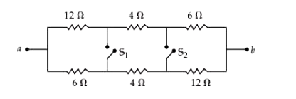
In the given figure switches S1andS2 are in open condition. The resistance across ab when the switches S1andS2 are closed is ……………… Ω.
 View Solution
The given Fig. 6.39, shows an inductor L and resistor R connected in parallel to a battery B through a switch S. The resistance of R is same as that of the coil that makes L. Two identical bulbs Pand Q are put in each arm of the circuit as shown.
(a) When S is closed, which of the two bulbs will light up earlier ?
(b) Will the bulbs be equally bright after some time? Justify your answer.View Solution
Knowledge Check
- Question 1 - Select One
Figure represents two bulbs B1 and B2, resistor R and an inductor L. When the switch S is turned off
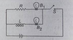 Aboth B1 and B2 die out promptlyBboth B1 and B2 die out with some delayCB1 dies out promptly but B2 with some delayDB2 dies out promptly but B1 with some delay
 - Question 2 - Select One
Figure represents two bulbs B1 and B2, resistor R and an inductor L. When the switch S is turned off
 Aboth B1 and B2 die out promptlyBboth B1 and B2 die out with some delayCB1 dies out promptly but B2 with some delayDB2 dies out promptly but B1 with some delay
 - Question 3 - Select One
Figure represents two bullbs B1 and B2resister R and inductor L. When the switch S in turned off,then
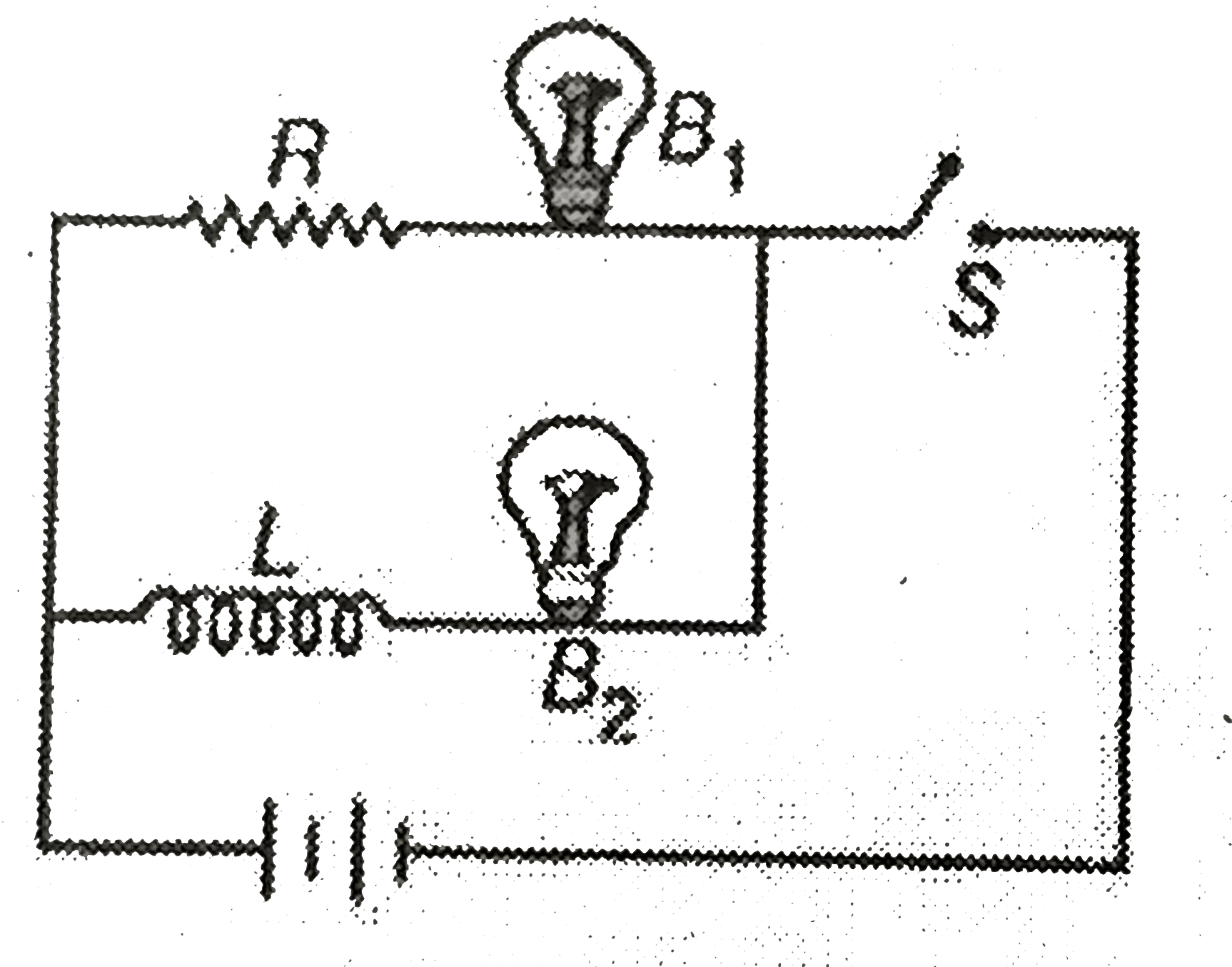 Aboth B1 and B2 die out promptlyBboth B1 and B2 die out with some selayCB1 dies out promptly but B2 with some selayDB_(2) dies out promptly but B1 with some delay
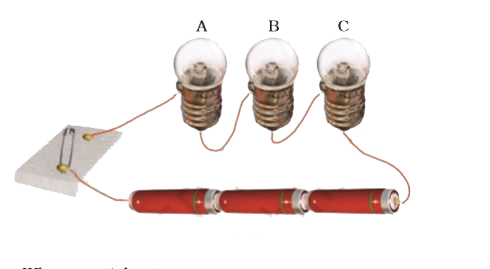
Three bulbs A, B, C are connected in a circuit as shown in Figure 14.2. When the switch is ‘ON’
 View Solution
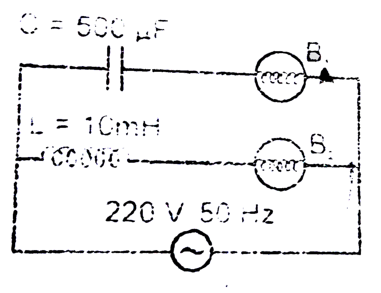
In the circuit shown in figure, if both the bulbs B1 and B2 are identical:
 View Solution
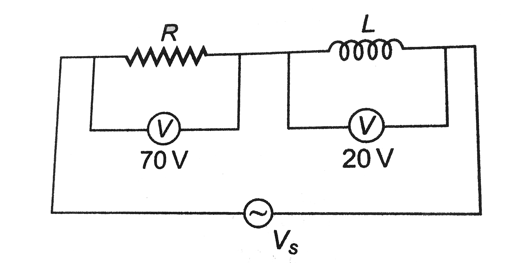
The adjoining figure shows an AC circuit with resistance R, inductance L and source voltage VS. Then
 View Solution
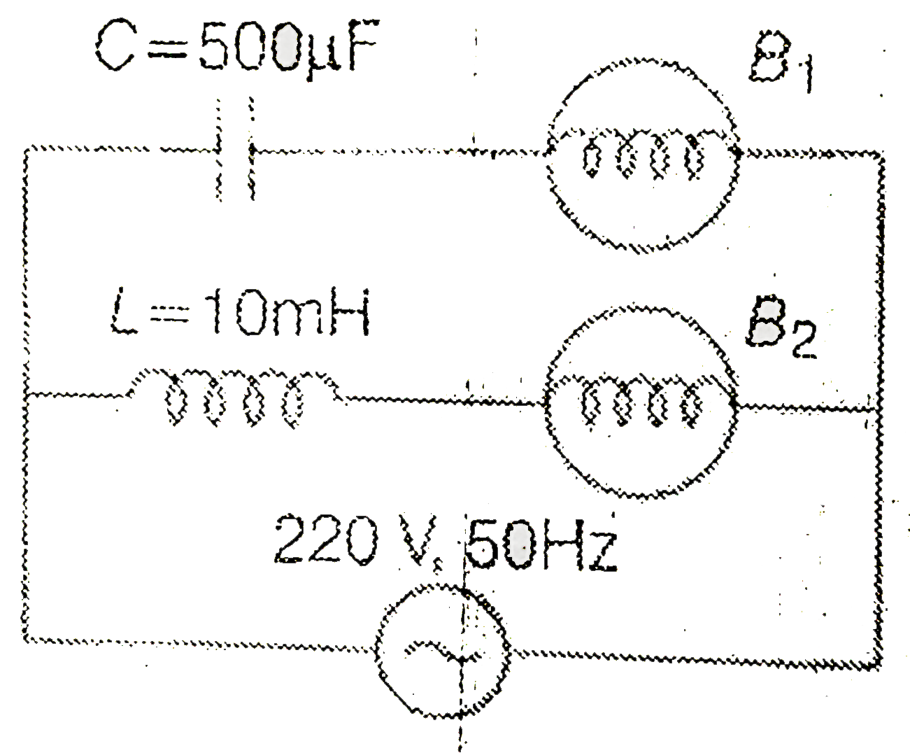
In the circuit shown in the figure, if both the bulbs B1andB2 are identical
 View Solution
An inductor L, a resistanc eR and two identical bulbs B1andB2 are connected to a battery through a switch S as shown in the figure . The resistance of coil having inductance L is also R. Which of the following statement gives the corrrect description of the happenings when the switch S is closed?
 View Solution

