The rest positions of the needles in a Milliammeter and Voltmeter when not being used in a circuit are as shown in the figure. The 'zero error' and 'least count' of these two instruments are :
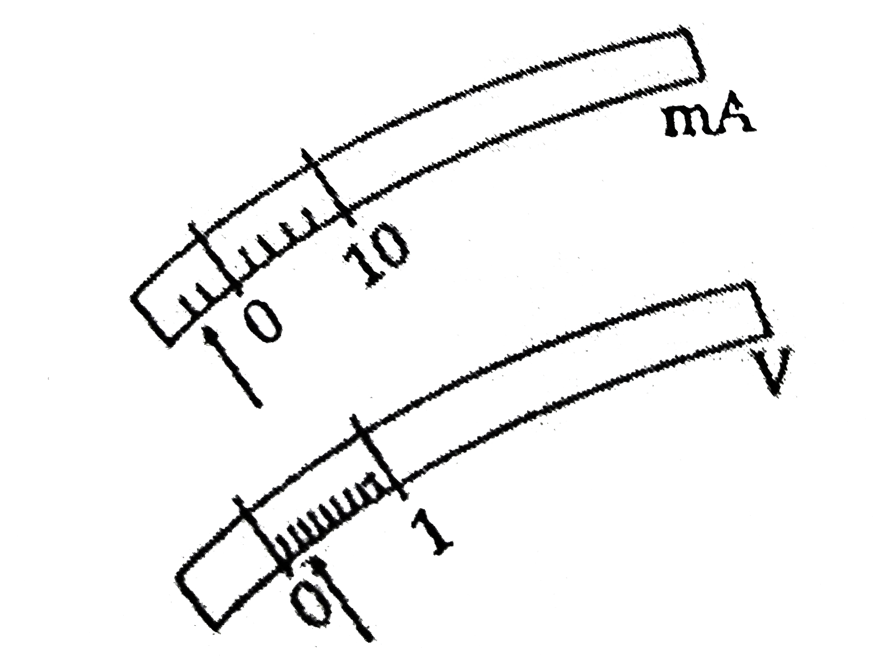
(+ 4 mA, - 0.2 V) and (1 mA, 0.1 V) respectively
(+ 4 mA, - 0.2 V) and (2 mA, 0.2 V) respectively
(- 4 mA, + 0.2 V) and (2 mA, 0.2 V) respectively
(- 4 mA, + 0.2 V) and (2 mA, 0.1 V) respectively
The correct Answer is:D
NA
Topper's Solved these Questions
- BOOK - LAKHMIR SINGH & MANJIT KAURCHAPTER - THE HUMAN EYE AND THE COLOURFUL WORLD EXERCISE - Long Answer Type Question3videos
THE HUMAN EYE AND THE COLOURFUL WORLD
- BOOK - LAKHMIR SINGH & MANJIT KAURCHAPTER - THE HUMAN EYE AND THE COLOURFUL WORLD EXERCISE - NCERT Book14videos
THE HUMAN EYE AND THE COLOURFUL WORLD
- BOOK - LAKHMIR SINGH & MANJIT KAURCHAPTER - THE HUMAN EYE AND THE COLOURFUL WORLD EXERCISE - Long Answer Type Questions2videos
THE HUMAN EYE AND THE COLOURFUL WORLD
- BOOK - LAKHMIR SINGH & MANJIT KAURCHAPTER - TEST PAPER 4EXERCISE - SECTION A10videos
TEST PAPER 4
Similar Questions
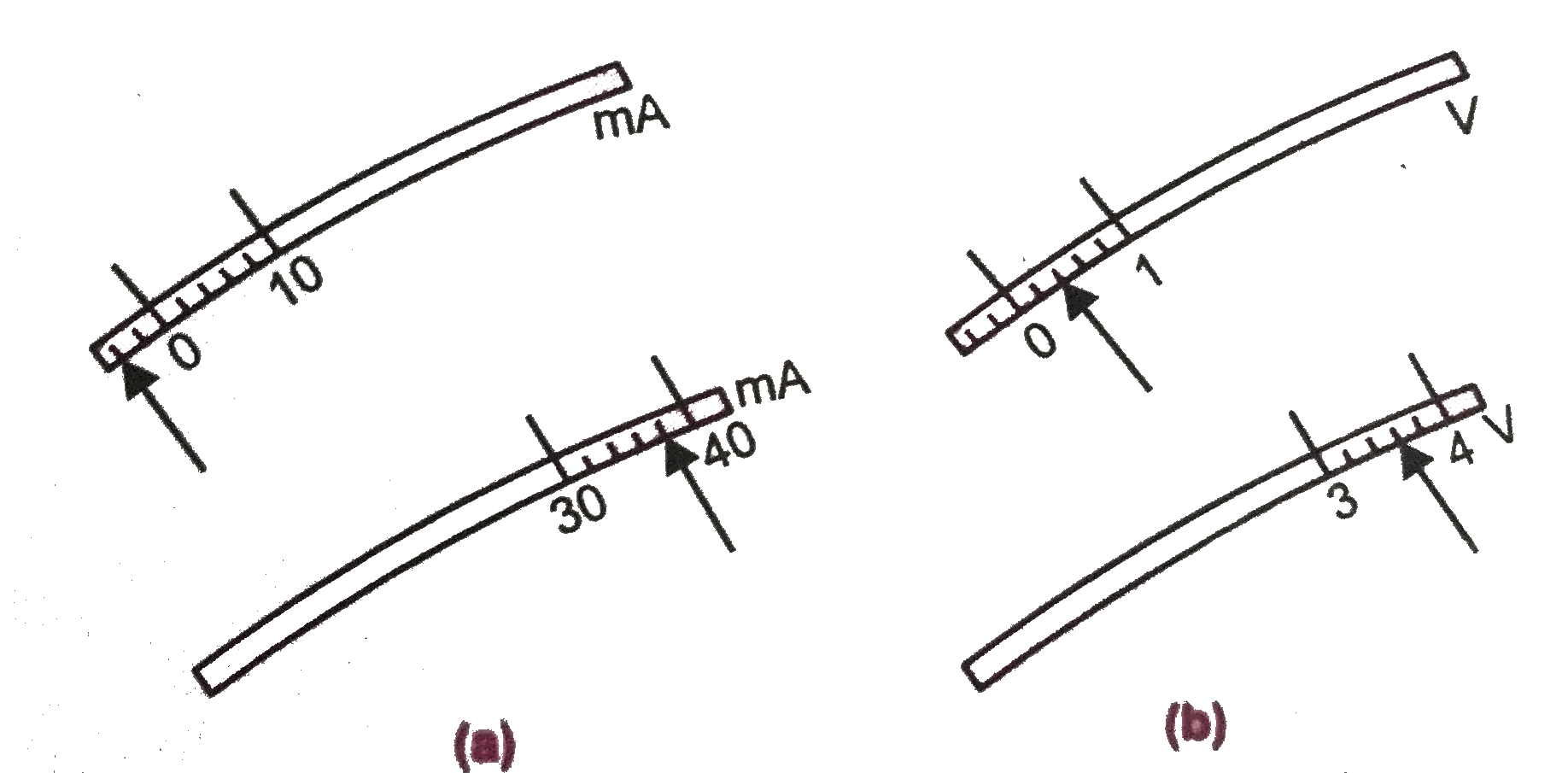
The rest positions of the needles in a milliammeter and voltmeter not in use are as shown in Fig. A. When a student uses these in his experiment, the readings of the needle are in the positions shown in Fig.B.

Find the corrected values of current and voltage in the experiment.View SolutionThe rest positions of the needles in a miliammeter and voltmeter not in use are as shown in (Fig. 3.61)(a). When a student uses these in his experiment, the readings of the needles are in the positions shown in (Fig. 3.61)(b). Find the corrected values of current and voltage in the experiment.
 .View Solution
Knowledge Check
- Question 1 - Select One
The rest positions of the needles in a milliammeter and voltmeter not in use are as shown in (Fig. 3.61)(a). When a student uses these in his experiment, the readings of the needles are in the positions shown in (Fig. 3.61)(b). Find the corrected values of current and voltage in the experiment.
 .A42 mA and 3.2 VB42 mA and 4.0 VC34 mA and 3.2 VD34 mA and 4.0 V
 - Question 2 - Select One
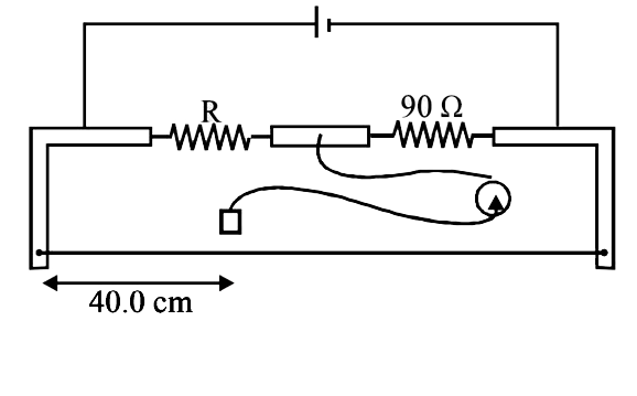
During an experiment with a metre bridge, the galvanometer shows a null point when the jockey is pressed at 40.0cm using a standard resistance of 90Ω, as shown in the figure. The least count of the scale used in the metre bridge is 1mm. The unknown resistance is
 A60±0.15ΩB135±0.56ΩC60±0.25ΩD135±0.23Ω
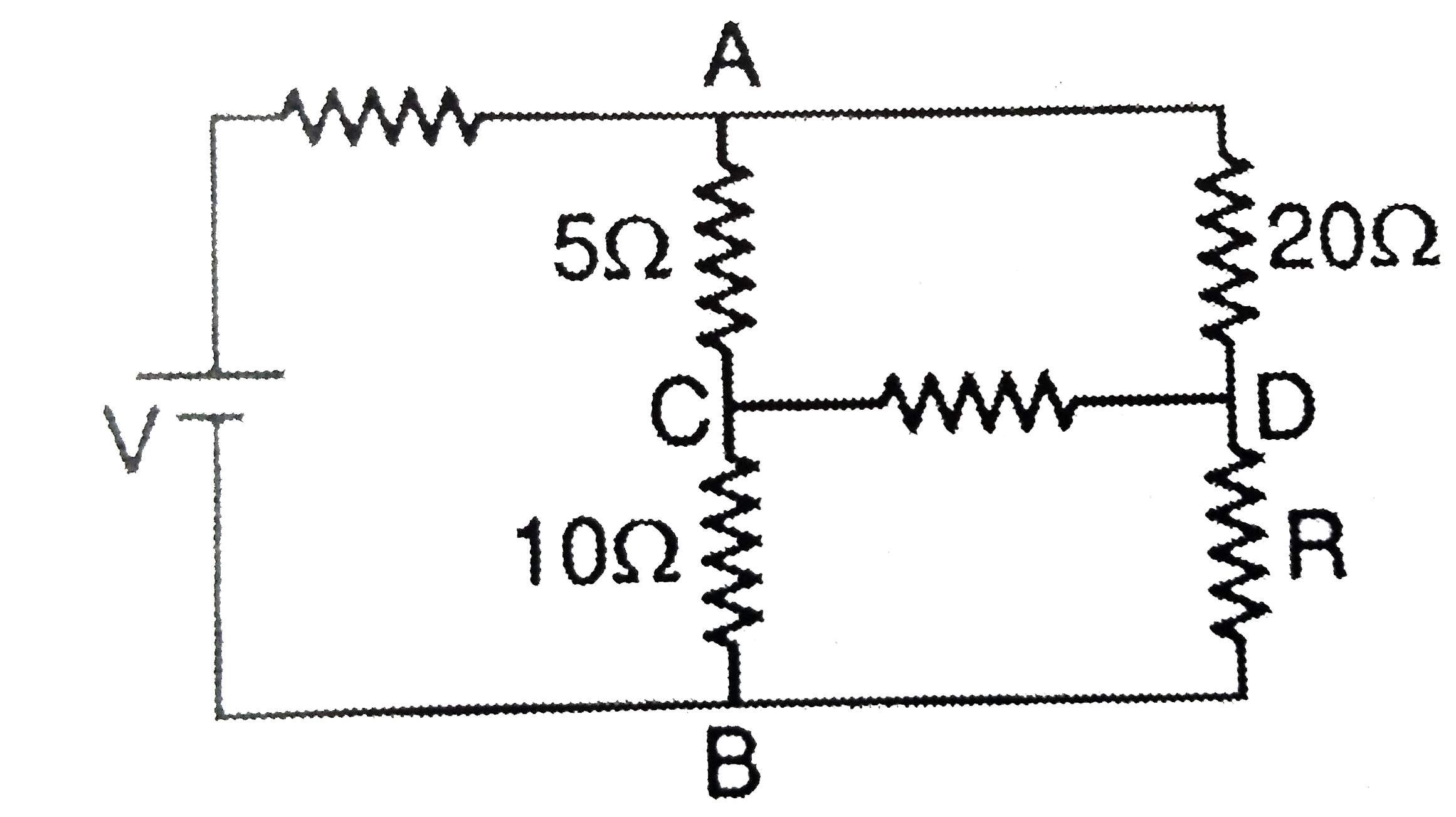
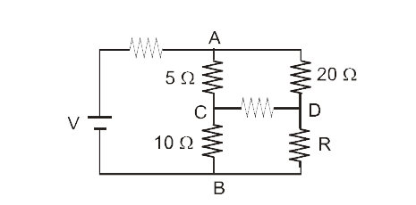
Determine the value of R in the circuit shown in figure, when the currnet in zero in the brance CD.
 View Solution
Determine the value of R in the circuit shown in
figure, when the current is zero in the branch CD.
 View Solution
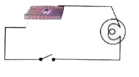
Will the compass needle show deflection when the switch in the circuit shown by figure is closed?
 View Solution
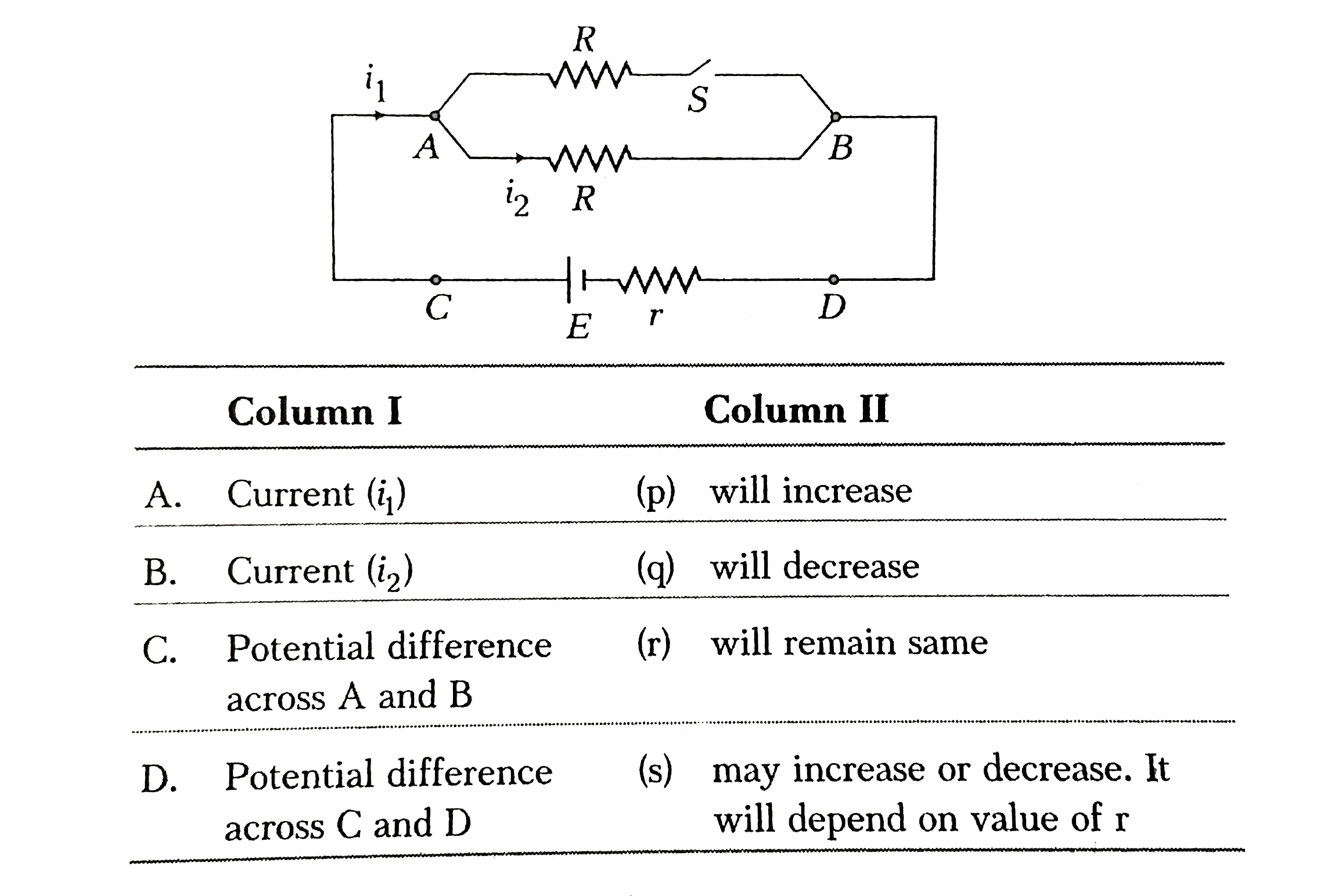
In the circuit diagram shown in figure match the following two columns when switch S is closed.
 View Solution
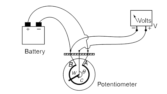
A rotary potentiometer has a circular resistance (C) and a conducting wiper (W) can rotate over it. An ideal battery and an ideal voltmeter are connected to it as shown in the figure. As the wiper is rotated on the circular resistance the reading of the voltmeter changes from zero to 20V. What is reading of the voltmeter when wiper is at angular position θ=120∘ ? Assume that resistance C is almost a complete circle and resistance of all connecting wires and knobs in the circuit is zero.
 View Solution
The given diagram represents a screw gauge. The circular scale is divided into 50 divisions and the linear scale is divided into millimeters. If the screw advances by 1mm when the circular scale makes 2 complete revolutions, find the least count of the instrument and the reading of the instrument in the figure.
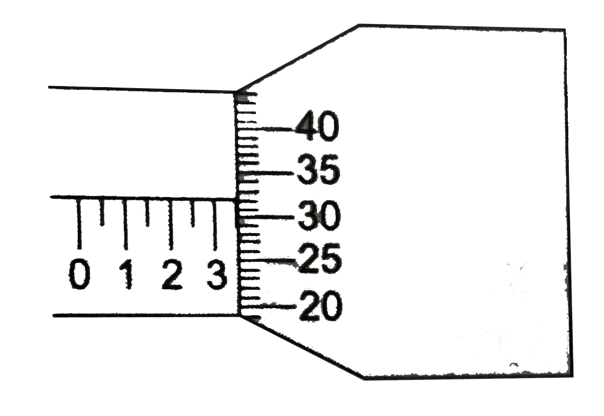 .View Solution

