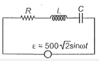
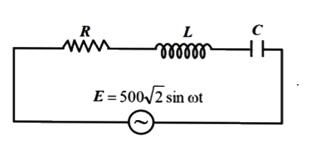
In a series RLC circuit the r.m.s. voltage across the resistor and the inductor are respectively 400 V and 700 V. If the equation for the applied Voltage is ε=500√2sinωt. then the peak voltage across the capacitor is

1200 V
1200√2V
400 V
400√2V
The correct Answer is:D
Step by step video & image solution for In a series RLC circuit the r.m.s. voltage across the resistor and the inductor are respectively 400 V and 700 V. If the equation for the applied <be> Voltage is epsilon = 500 sqrt(2) sin omegat. then the peak voltage across the capacitor is by Physics experts to help you in doubts & scoring excellent marks in Class 12 exams.
Updated on:21/07/2023Similar Questions
In the series L−C−R circuit shown in the figure, the rms voltage across the resistor and inductor are 400 V and 700 V respectively. If the applied voltage is E=500√2sin(ωt), then the peak voltage across the capacitor is

View SolutionIn a series LCR circuit, rms voltage across inductor and capacitor are found ot be 8 V and 5 V respectively. If applied voltage is 5 volts, then what is rms voltage across resistance in volts ?
View Solution
Knowledge Check
120 V AC voltage is applied to 10 ohm resistance. The peak voltage across the resistor is
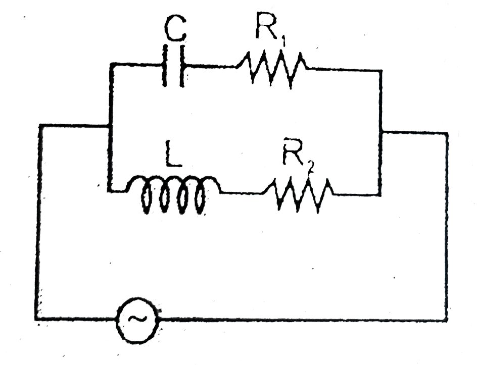
A120 VB120√2VC120√2VDnone of theseIn the circuit the rms value of voltage across the capacitor C, inductor L and resister R1 are respectively 5√5V, 10 V and 5V. Then the peak voltage a cross R2 is
 A7VB10VC15VD5√2V
In an LCR series circuit the voltages across R,L and C at resonance are 40Vand60V respectively the applied voltage is .
A60VB40VC160VD√(40)2+(120)2V
In a series LCR circuit, the voltages across an inductor, a capacitor and a resistor are 30 V, 30 V, 60 V respectively. What is the phase difference between the applied voltage and the current in the circuit ?
View SolutionIn a series LCR circuit the voltage across an inductor, capacitor and resistor are 20 V, 20 V and 40 V respectively. The phase difference between the applied voltage and the current in the circuit is
View SolutionSTATEMENT-1: In a series LCR circuit at resonance, the voltage across the capacitor or inductor may be more than the applied voltage.
STATEMENT-2: At resonance in a series LCR circuit, the voltages across inductor and capacitor are out of phase.
View SolutionIn an LCR series ac circuit the voltage across L,C and R are V1,V2 and V3 respectively The voltage of the source is .
View SolutionIn a series L-C-R circuit the voltage across resistance , capacitance and inductance is 10 V each. If the capacitance is short circuited, the voltage across the inductance will be
View Solution
