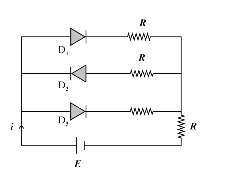
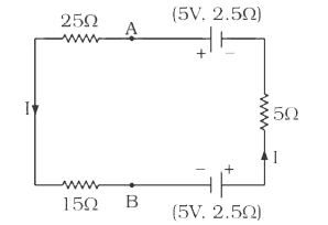
In the following circuits, PN - junction diodes D1,D2andD3 are ideal for the following potential of A and B, the correct increasing order of resistance between A and B will be
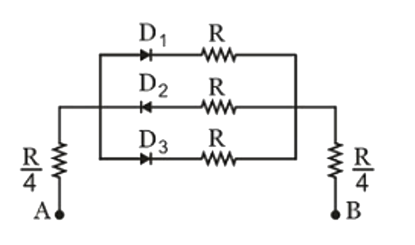
(i) −10V,−5V
(ii) −5V,−10V
(iii) −4V,−12V
(i) lt (ii) lt (iii)
(iii) lt (ii) lt (i)
(ii) = (iii) lt (i)
(i) = (iii) lt (ii)
The correct Answer is:C
Step by step video, text & image solution for In the following circuits, PN - junction diodes D_(1),D_(2) and D_(3) are ideal for the following potential of A and B, the correct increasing order of resistance between A and B will be (i) -10V, -5V (ii) -5V, -10V (iii) -4V, -12V by Physics experts to help you in doubts & scoring excellent marks in Class 12 exams.
Updated on:21/07/2023Topper's Solved these Questions
Similar Questions
Knowledge Check
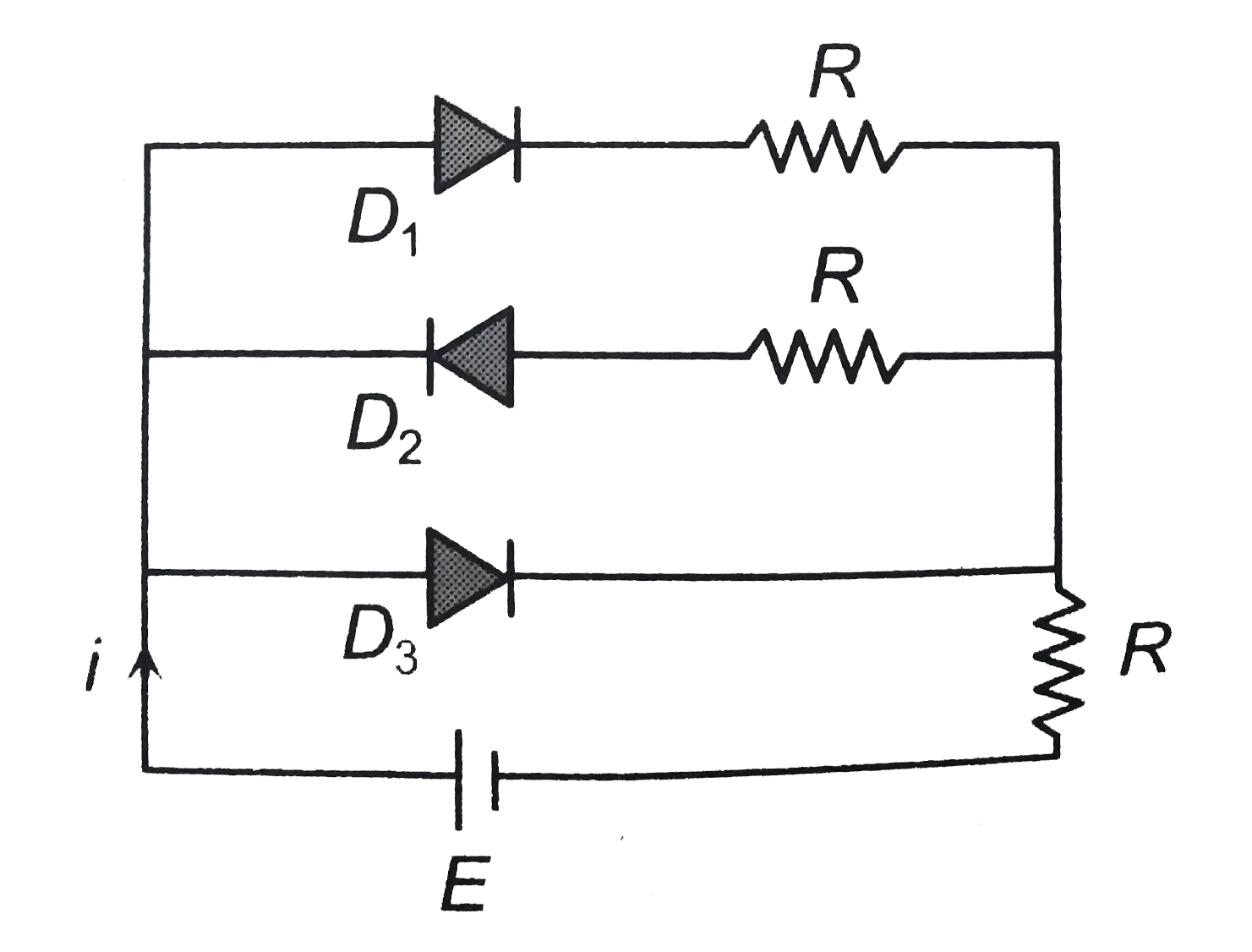
In the following circuit of PN junction diodes D1,D2 and D3 are ideal then i is
 AE/RBE/2RC2E/3RDZero
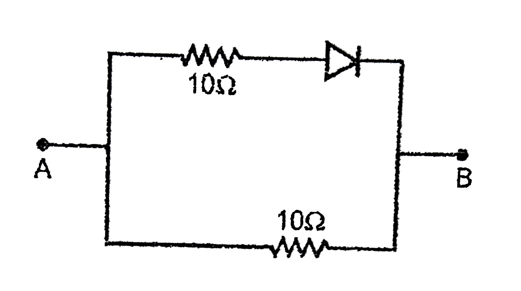
If VA and VB denote the potentials of A and B, then the equivalent resistance between A and B in the adjoint electric circuit isA10 ohm if VA>VBB5 ohm if VA<VBC5 ohm if VA>VBD20 ohm if VA>VBVA and VB denote potential of A and B, then the equivalent resistance between A and B in the adjoining circuit is (ideal diode).
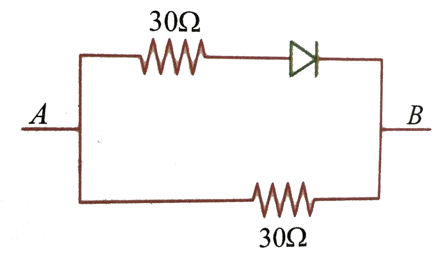 .A15ΩifVA>VBB30ΩifVA<VBCboth 1 and 2Dneither 1 nor 2
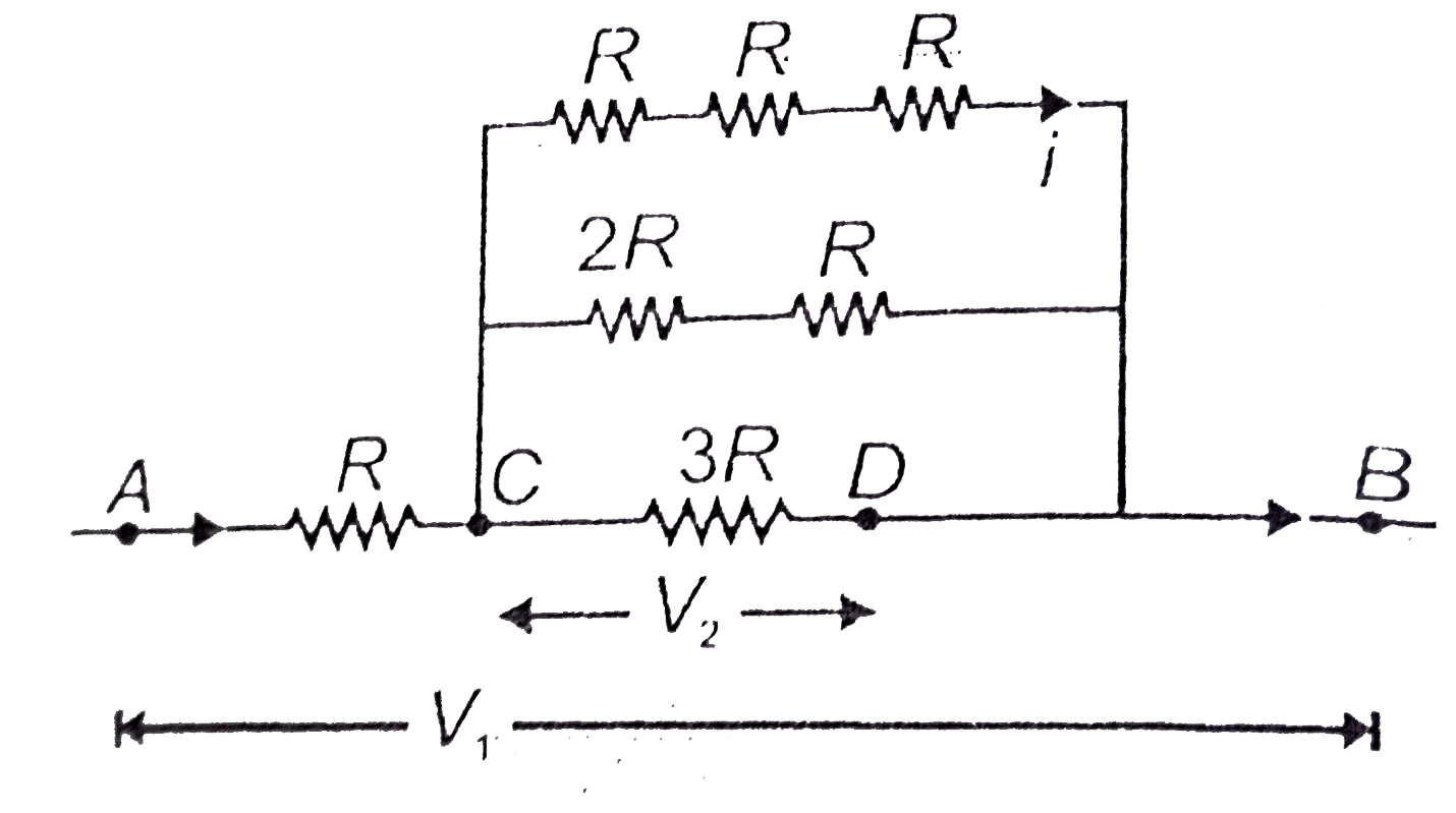
In the circuit shown, the potential differences, V1 ( between A and B ) and V2 ( between C and D ), are
View SolutionVAandVB denot potentils of A and B then the equivalent resistance of A and B, then the equivalent resistance between A and B in the adjoining circuit is (ideal diode)

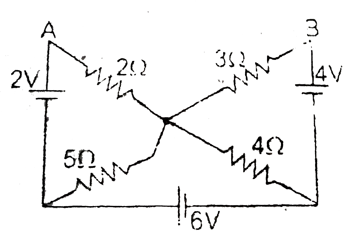
View SolutionPotential difference between points A and B (i.e. VA−VB) is -----
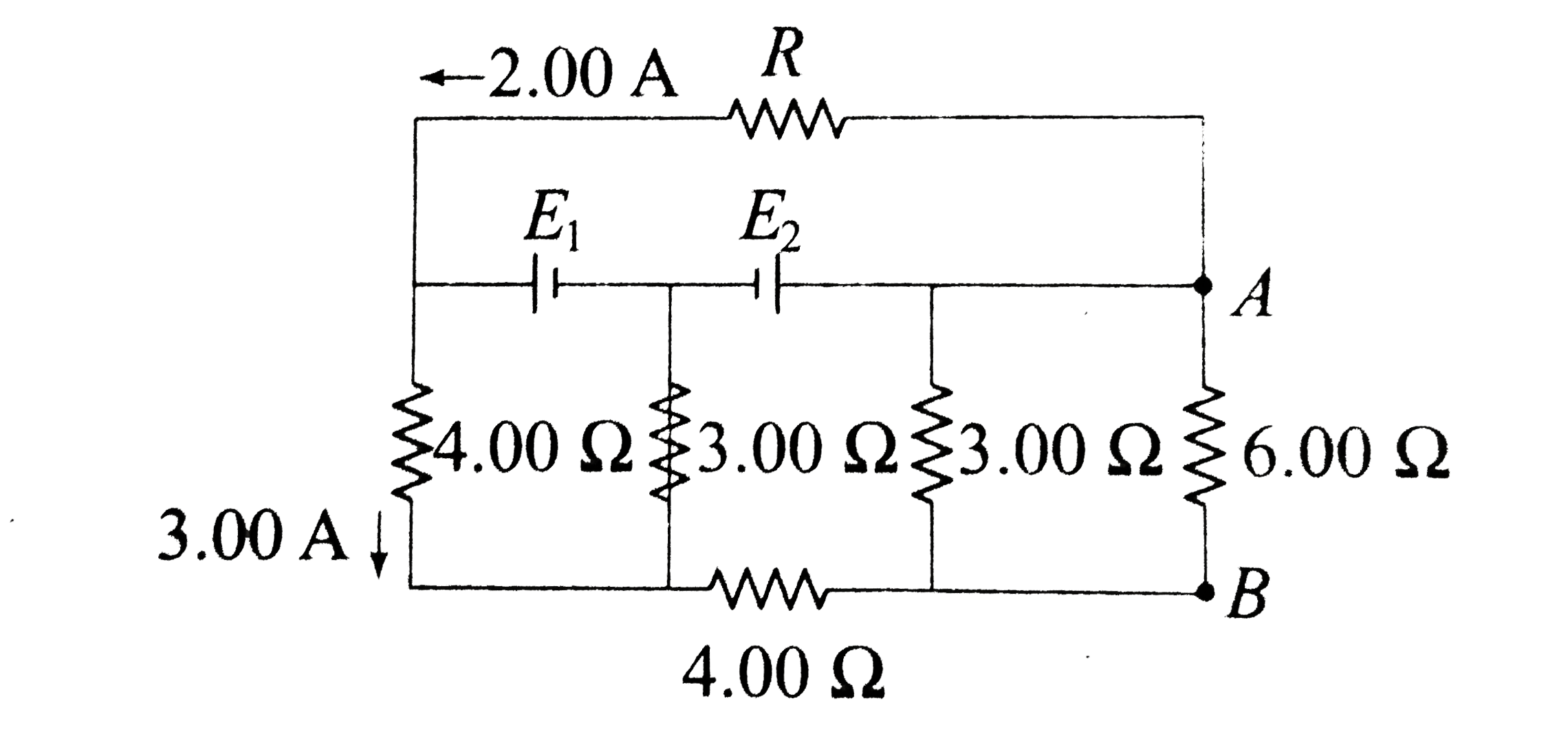
View SolutionIn the circuit shown in figure, E1andE2 are two ideal sources of unknown emfs. Some currents are shown. Potential difference appearing across 6Ω resistance is VA−VB=10V.
View SolutionTwo condensers C1 and C2 in a circuit are jhioned as shown in . The potential fo point A is V1 and that of B is V2 . The potential of point D will be

View Solution

