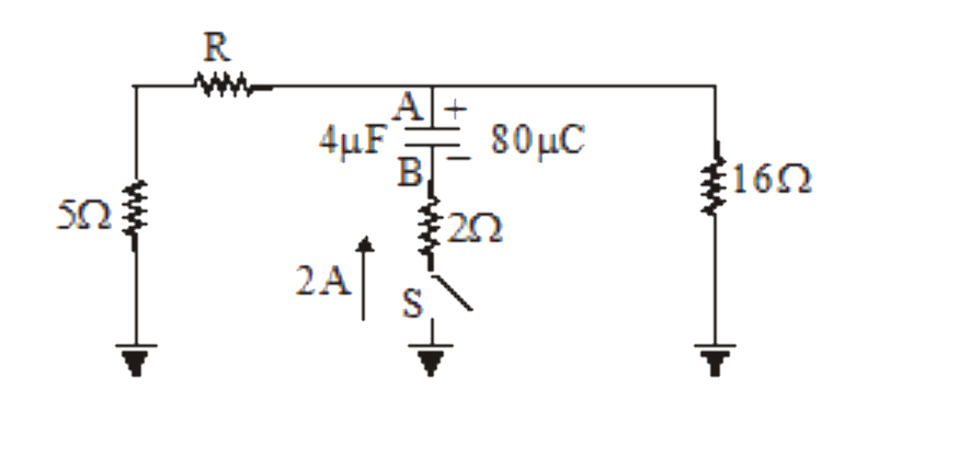
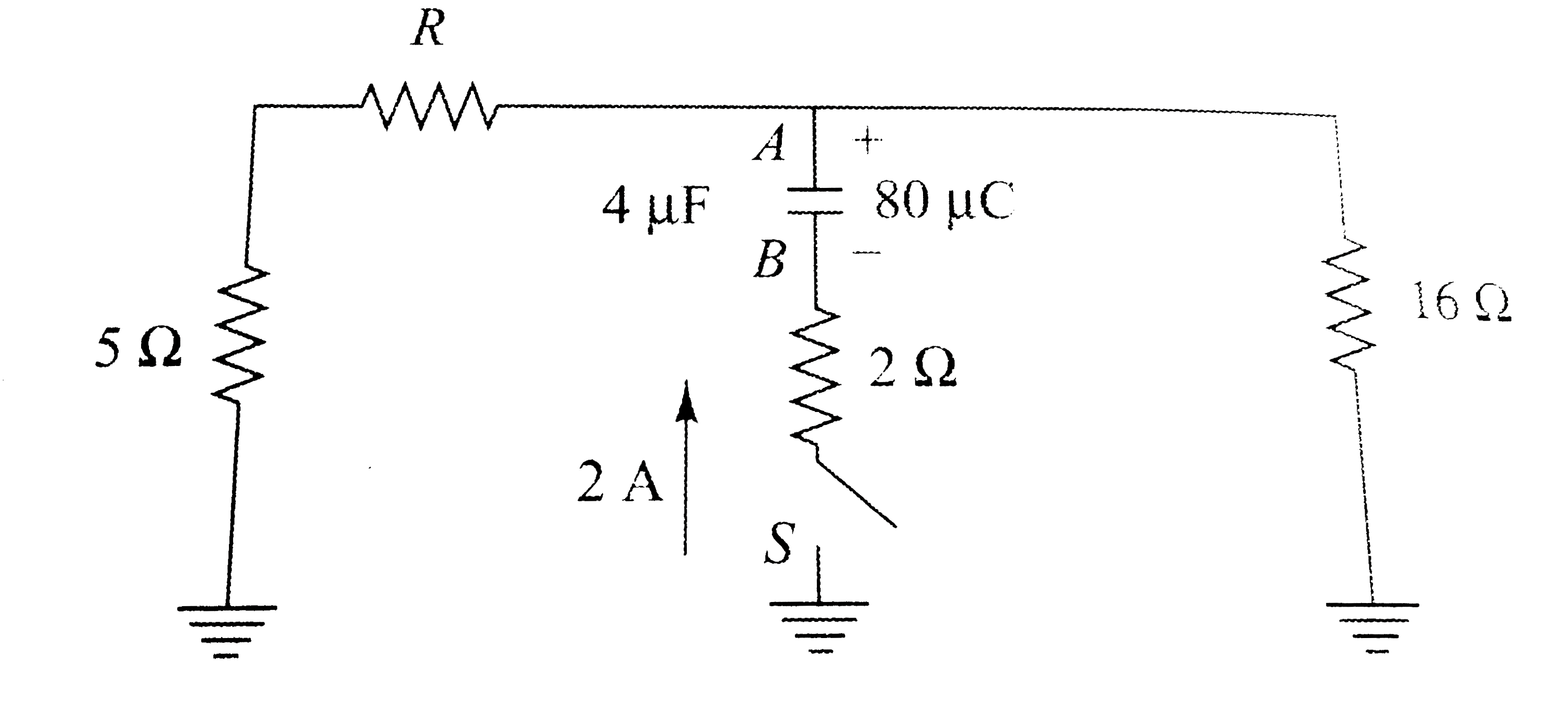
An 80μC charge is given to the 4μF capacitor in the circuit shown in the figure so that the upper plate A is positively charged. An unknown resistance R is connected in the left limb. As soon as the switch S in the central limb is closed, a current of 2 A flows through the 2Ω resistor in the central limb. The capacitive time constant for the circuit is
56μs
8μs
200μs
40μs
The correct Answer is:D
Step by step video, text & image solution for An 80muC charge is given to the 4muF capacitor in the circuit shown in the figure so that the upper plate A is positively charged. An unknown resistance R is connected in the left limb. As soon as the switch S in the central limb is closed, a current of 2 A flows through the 2Omega resistor in the central limb. The capacitive time constant for the circuit is by Physics experts to help you in doubts & scoring excellent marks in Class 12 exams.
Updated on:21/07/2023Topper's Solved these Questions
Similar Questions
Knowledge Check
An 80μC charge is given to the 4μF capacitor in the circuit shown in Fig. so the upper plate A is positively charged. An unknown resistance R is connected in the left limb. As soon as the switch S in the central limb is closed, a current of 2 A flows through the 2Ω resistor in the central limb. The capacitive time constant for the circuit is
 A56μsB8μsC200μsD40μs
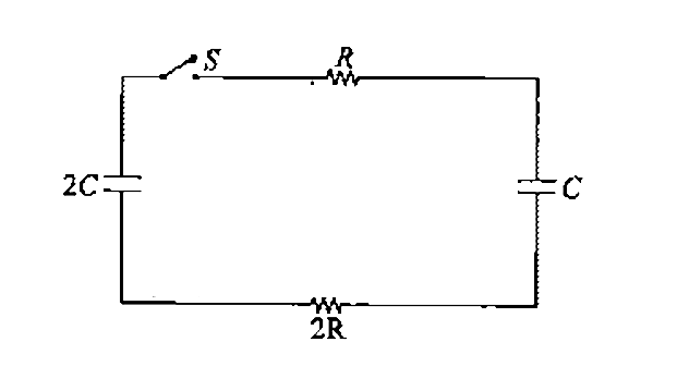
In the circuit shown in figure-3.345 the capacitor of capacitance C is charged to a potential difference V. The current in the circuit just after the closing of switch S is :
 AV3RB3VRCV2RDzero
In the circuit shown in the figure, if switches S1 and S2 have been closed for a long time, then charge on the capacitor.
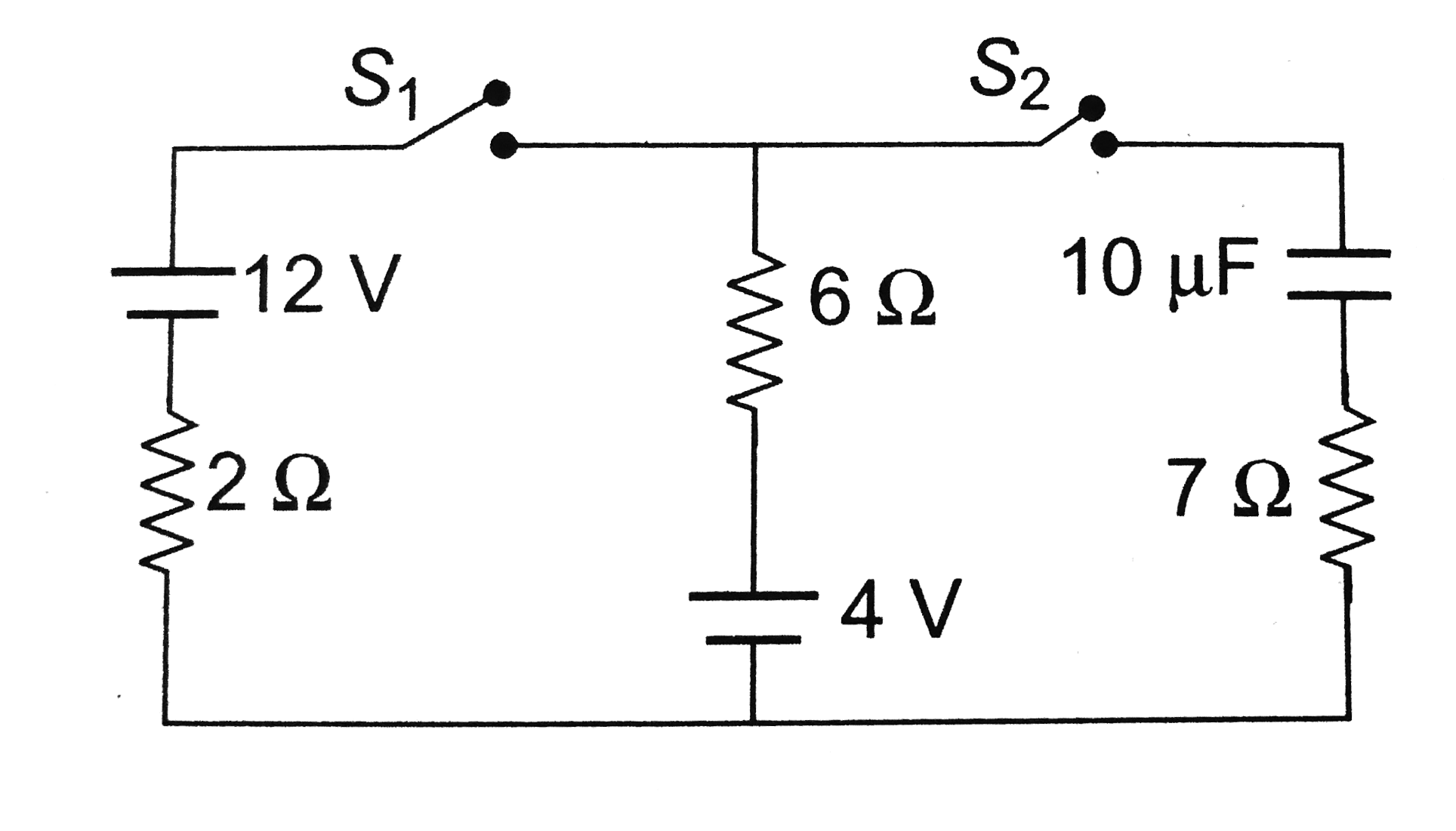 Ais 100μCBincreases to 200μC if one third of the gap of the capacitor's plates is filled with a dielectric (K=2) of same areaCboth (a) and (b) aboveDcharge on the capacitor remains unchanged if one third of the gap of the capacitor's plates is filled with a dielectric (K=2) of same area.
In the circuit shown in figure 3.242 capacitor is charged with 50μC charge. Find the current in 4Ω resistance just after switch S is closed.
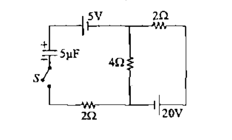
View SolutionFor the circuit shown in figure below, At t = 0, switch is closed, the initial current through resistor and final charge on capacitor are
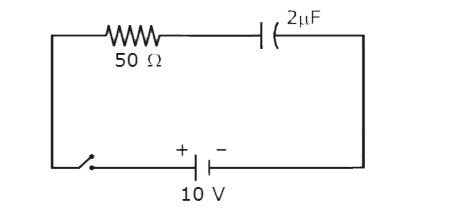
View SolutionIn connection with the circuit drawn below, the value of current flowing through 2 kΩ resistor is _____ ×10−4A

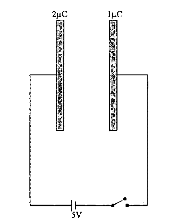
View SolutionA parallel plate capacitor of capacitance 0.1μF is shown in the figure. Its two plates are given charges 2μC and 1μC. Find the value of heat dissipated after switch is closed :
View SolutionIn the circuit shown in figure switch S is closed at time t=0
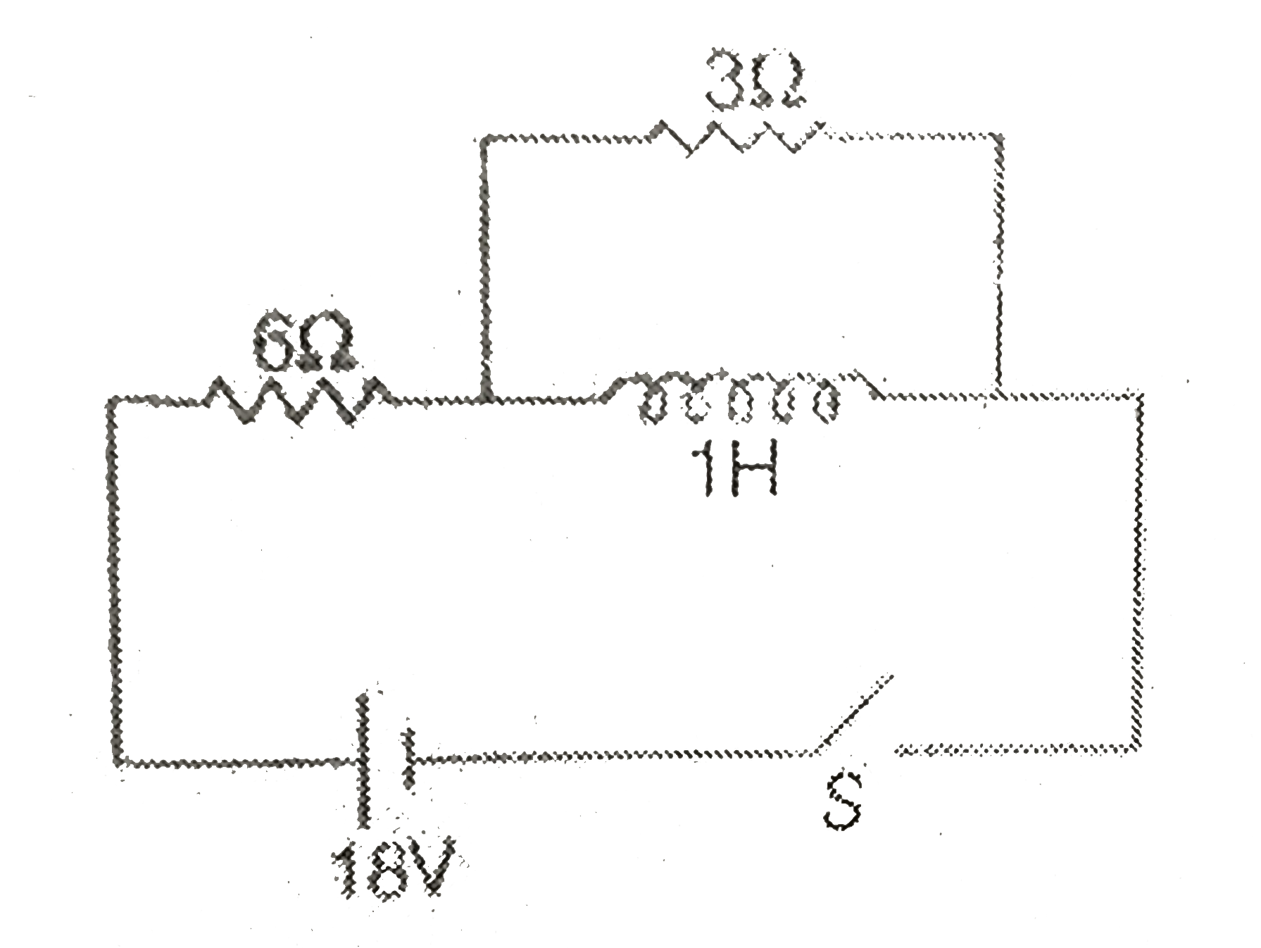
At what time current through 3Ω resistance and 1H inductor are equal?
View Solution

