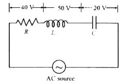
In series L-C-R circuit as shown in figure the voltage of the source is
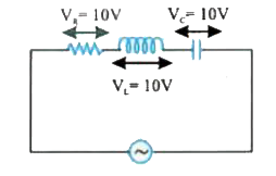
Step by step video & image solution for In series L-C-R circuit as shown in figure the voltage of the source is by Physics experts to help you in doubts & scoring excellent marks in Class 12 exams.
Updated on:21/07/2023Similar Questions
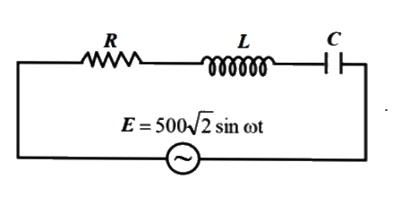
In the series L−C−R circuit shown in the figure, the rms voltage across the resistor and inductor are 400 V and 700 V respectively. If the applied voltage is E=500√2sin(ωt), then the peak voltage across the capacitor is
View SolutionIn a series CR circuit shown in figure,the applied voltage is 10V and the voltage across capacitor is found to be 8V
View Solution
Knowledge Check
In the L-C-R circuit as shown in figure,
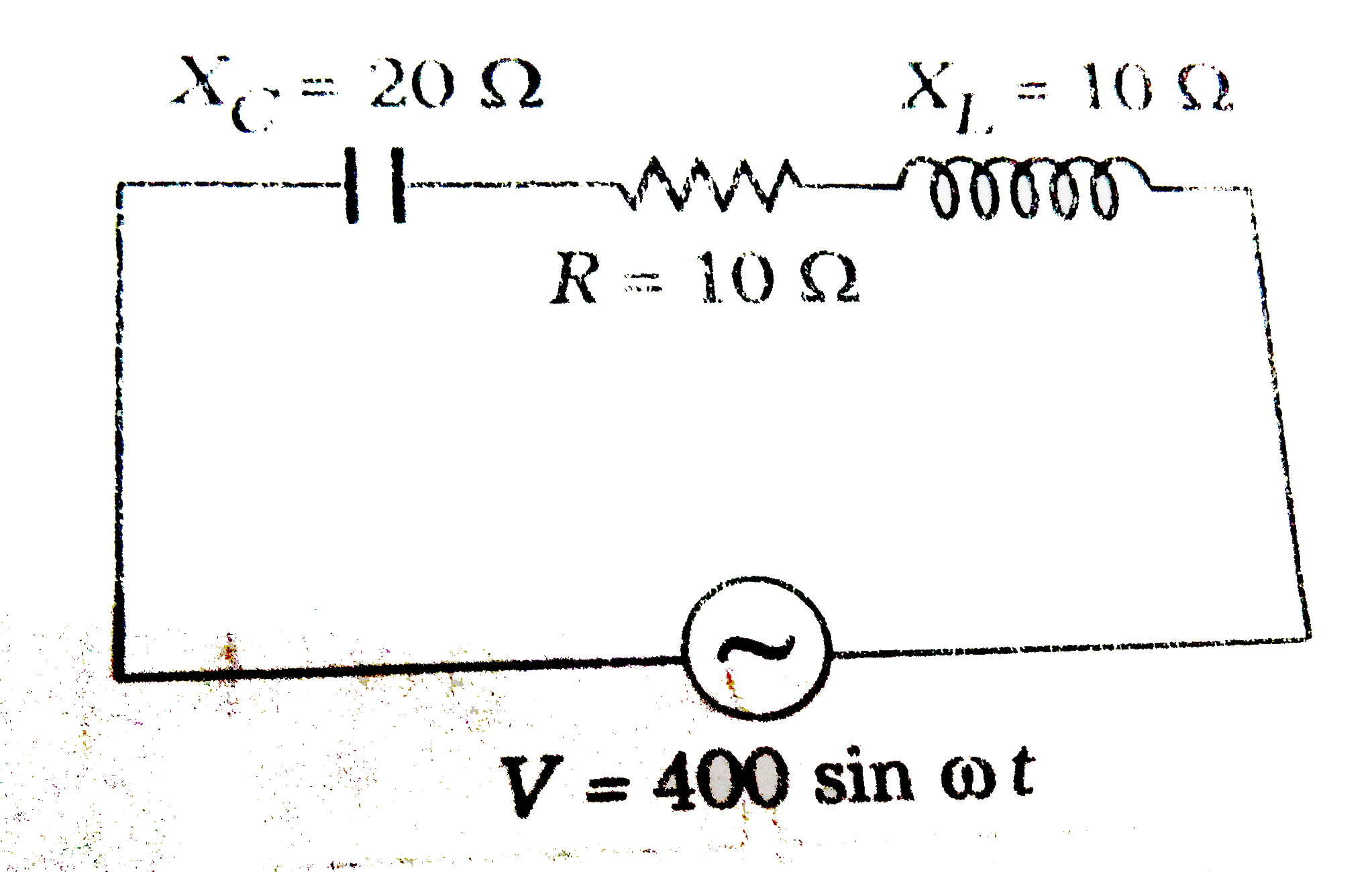 ACurrent will lead the voltageBRuns value of current is 20 ACPower factor of the circuit is 1√2DVoltage drop across resistance is 200 V
In L−C−R series circuit
Acurrent may achieve same value for two different value of frequencyBcurrent can not achieve same value for two different values of frequencyCcurrent is maximum for a maximum value of frequencyDnone of theseIn a series C−R circuit shown in figureure, the applied voltage is 10V and the voltage across capacitor is found to8V. The voltage across R, and the phase difference between current and the applied voltage will respectively be
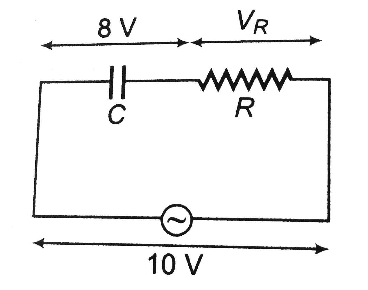 .A6V,tan−1(43)B3V,tan−1(34)C6V,tan−1(34)Dnone of these
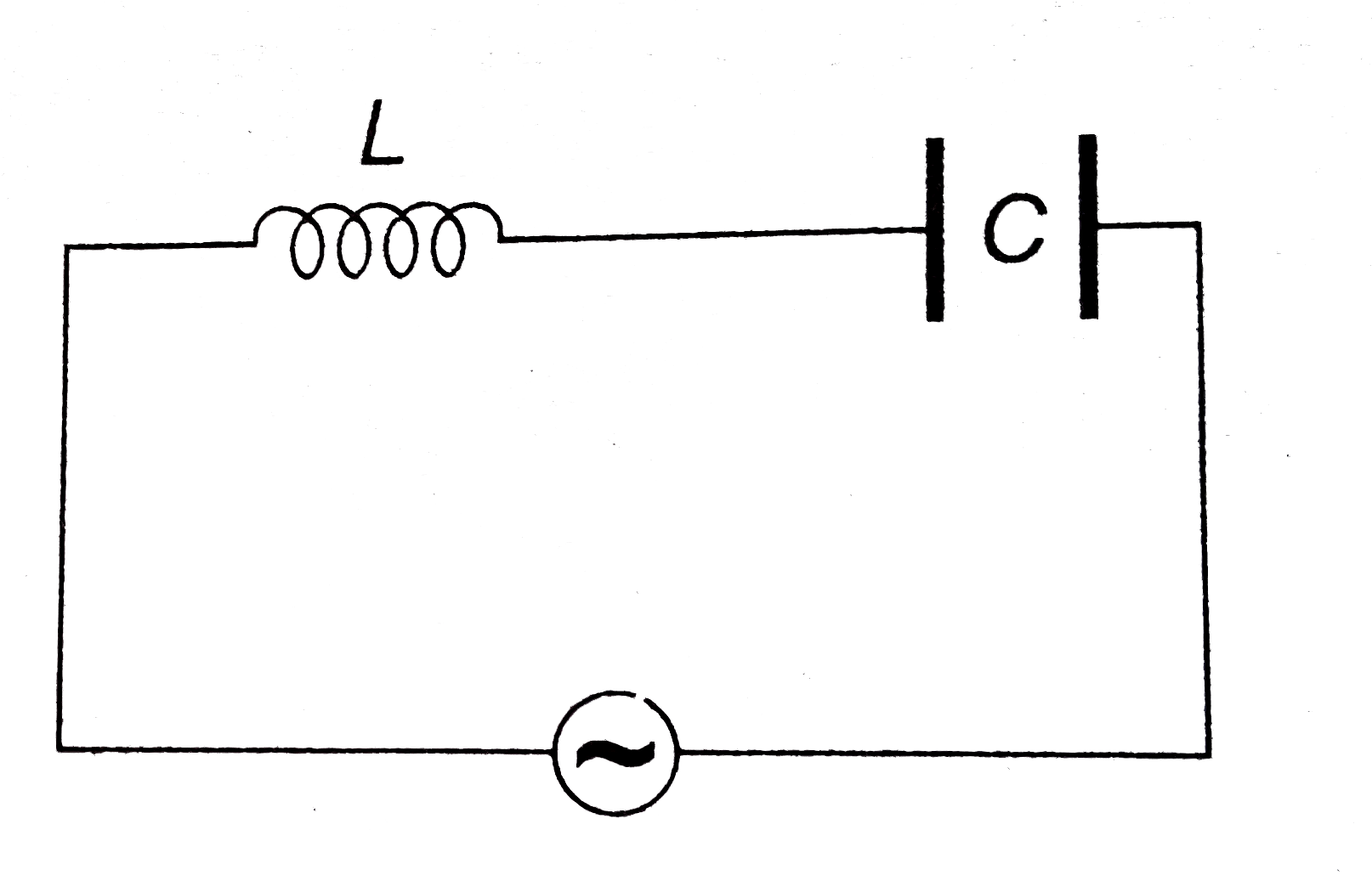
In a series L-C-R circuit shown in the figure , what is the resonance frequency and the current at the resonating frequency?
View SolutionIn the circuit shown in figure the voltage in L and in C are
 .
.
View SolutionIn L−C−R series AC circuit,
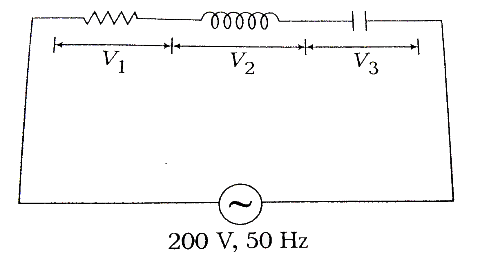
View SolutionFor series L-C-R circuit shown in the figure, the readings of V1 and V3 are same and each equal to 100 V .Then
View SolutionIn series LCR circuit, the voltages across R, L and C shown in figure. The voltage of applied source is
View Solution
