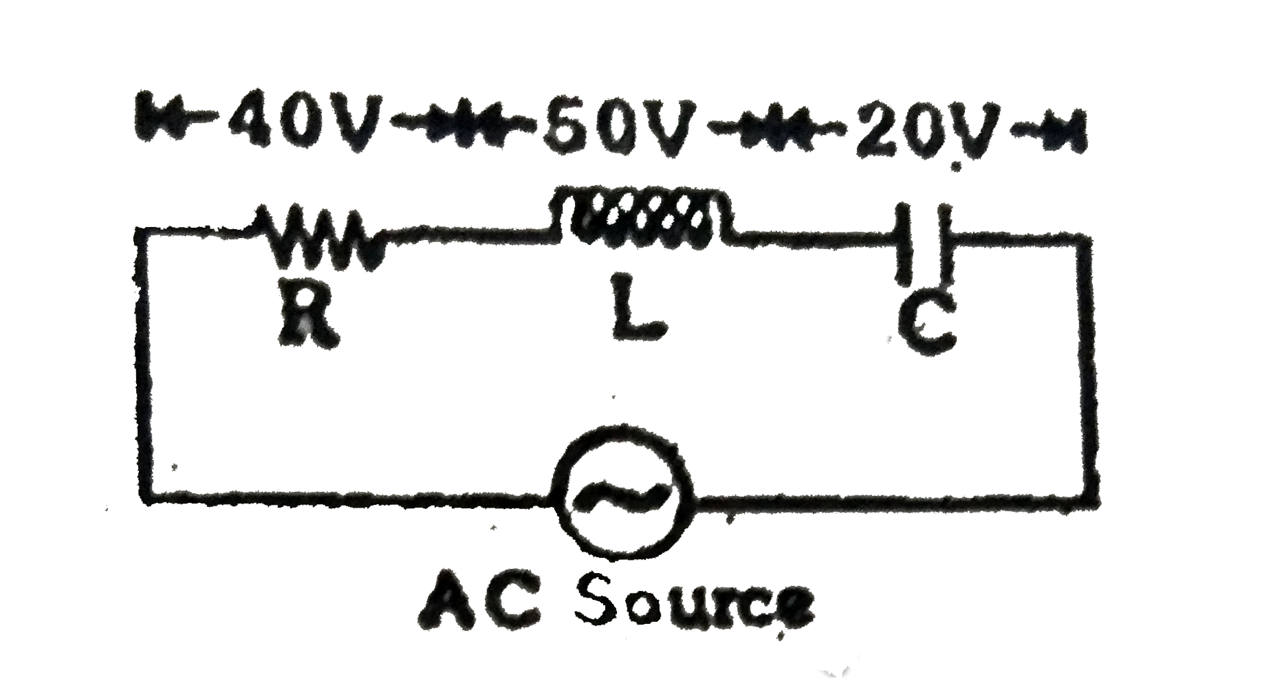
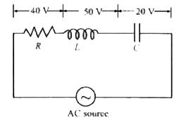
If in a series L-C-R ac circuit, the voltages across R,L,C are respectively. Then the voltage of applied AC source is always equal to
To solve the problem regarding the voltage in a series L-C-R AC circuit, we will follow these steps:
1. Understand the Circuit Components:
- In a series L-C-R circuit, we have three components: a resistor (R), an inductor (L), and a capacitor (C). The voltages across these components are denoted as V1 (across R), V2 (across L), and V3 (across C).
2. Phasor Representation:
- The voltages across the components can be represented as phasors. The voltage across the resistor V1 is in phase with the current, while the voltage across the inductor V2 leads the current by 90 degrees, and the voltage across the capacitor V3 lags the current by 90 degrees.
3. Using the Phasor Diagram:
- In the phasor diagram, the voltage across the inductor V2 and the voltage across the capacitor V3 are 180 degrees apart (one leads and the other lags). Therefore, we can express the relationship between these voltages using vector addition.
4. Applying Pythagorean Theorem:
- The total voltage V supplied by the AC source can be found using the Pythagorean theorem. The voltage across the resistor V1 is the horizontal component, while the net effect of V2 and V3 can be treated as vertical components. Thus, we can write:
V=√V21+(V2−V3)2
5. Final Expression:
- Therefore, the voltage of the applied AC source is given by:
V=√V21+(V2−V3)2
- In a series L-C-R circuit, we have three components: a resistor (R), an inductor (L), and a capacitor (C). The voltages across these components are denoted as V1 (across R), V2 (across L), and V3 (across C).
- The voltages across the components can be represented as phasors. The voltage across the resistor V1 is in phase with the current, while the voltage across the inductor V2 leads the current by 90 degrees, and the voltage across the capacitor V3 lags the current by 90 degrees.
- In the phasor diagram, the voltage across the inductor V2 and the voltage across the capacitor V3 are 180 degrees apart (one leads and the other lags). Therefore, we can express the relationship between these voltages using vector addition.
- The total voltage V supplied by the AC source can be found using the Pythagorean theorem. The voltage across the resistor V1 is the horizontal component, while the net effect of V2 and V3 can be treated as vertical components. Thus, we can write:
V=√V21+(V2−V3)2
- Therefore, the voltage of the applied AC source is given by:
V=√V21+(V2−V3)2
Topper's Solved these Questions
- ALTERNATING CURRENTBook:NARAYNAChapter:ALTERNATING CURRENTExercise:Assertion & Reason
Explore 14 Videos
- ALTERNATING CURRENTBook:NARAYNAChapter:ALTERNATING CURRENTExercise:LEVEL - I (C.W)
Explore 23 Videos
- ALTERNATING CURRENTBook:NARAYNAChapter:ALTERNATING CURRENTExercise:LEVEL - II(H.W)
Explore 13 Videos
- ATOMIC PHYSICSBook:NARAYNAChapter:ATOMIC PHYSICSExercise:LEVEL-II (H.W)
Explore 14 Videos
Similar Questions
In a series L–C–R circuit, voltages across inductor, capacitor, and resistor are VL,VCandVR respectively. What is the phase difference between (i) VLandVR (ii) VLandVC ?
View SolutionIn series LCR circuit, the voltages across R, L and C are shown in the figure. The voltage of applied source

View Solution
Knowledge Check
In an LCR series ac circuit the voltage across L,C and R are V1,V2 and V3 respectively The voltage of the source is .
A√(V1−V2)2+V23B√V21+(V2−V23C√V22+(V1−V3)2DV1+V2+V3In an LCR circuit, the voltages across the components are VL,VC and VR respectively. The voltage of source will be -
A[VR+VL+VC]B[(V2R+V2L+V2C]1/2C[(V2R+(VL+VC)2]1/2D[(V2R+(VL−VC)2]1/2In an LCR series circuit the voltages across R,L and C at resonance are 40Vand60V respectively the applied voltage is .
A60VB40VC160VD√(40)2+(120)2V
In series LCR circuit, the voltages across R, L and C shown in figure. The voltage of applied source is

View SolutionIn an LCR series circuit the rms voltages across R,L and C are foundd to be 10V,10V and 20V respectively. The rms voltage across the entire combination is
View SolutionIn a series resonant circuit, the AC voltage across resistance R, inductance L, and capacitance C are 5V,10V and 10V respectively. The AC voltage applied to the circuit will be
View SolutionIn an L-C-R circuit the AC voltage across R, L and C comes out as 10 V , 10 V and 20 V respectively . The voltage across the enter combination will be
View SolutionIn a series L.C.R. circuit, the potential drop across L, C and R respectively are 40V, 120V and 60V . Them the source voltage is
View Solution