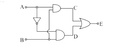
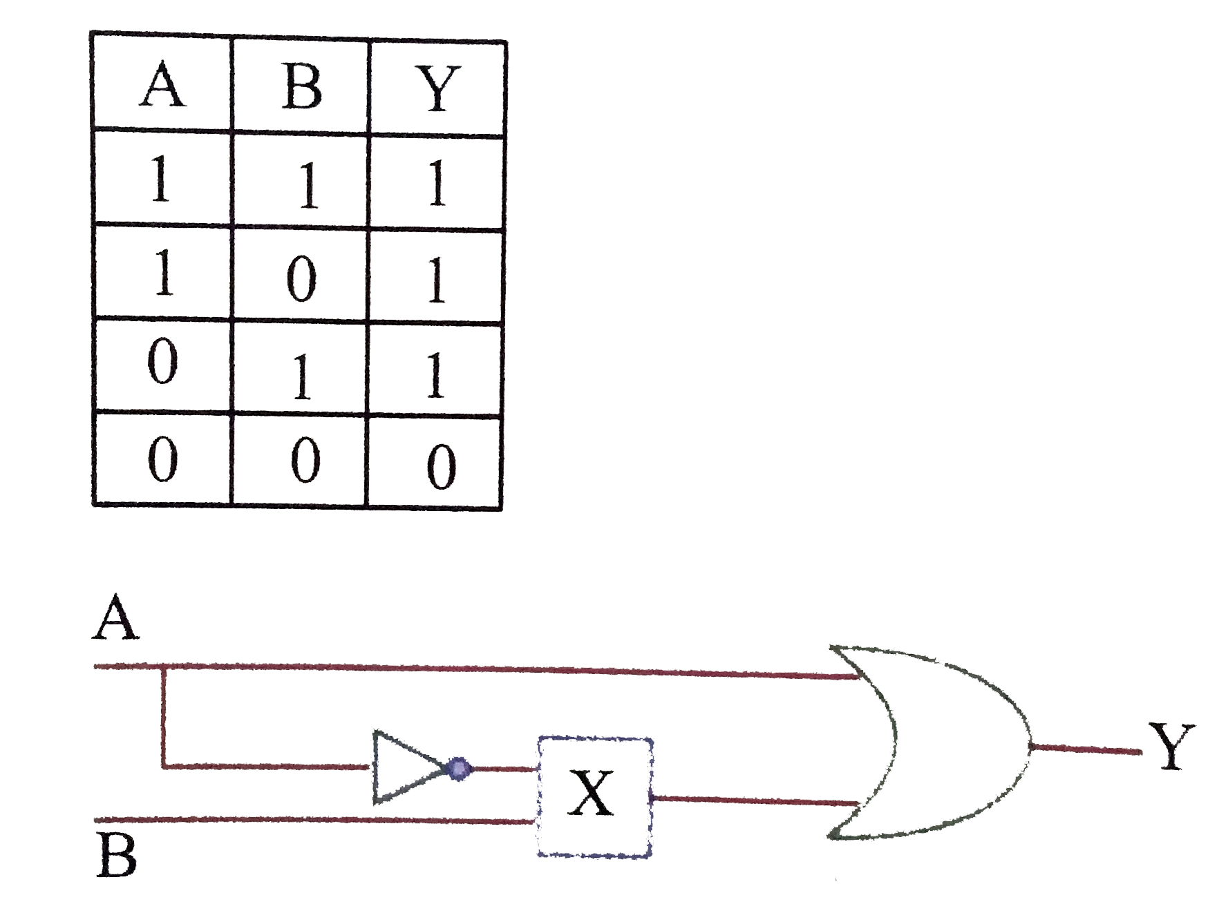
The logic circuit and its truth table are given, what is the gate X in the diagram
 .
.
Video Solution
Text Solution
From the truth table we note that Y+B i.e., it is for OR gate (or)
A+X=A+B=A+B.(A+¯¯¯A)(∴A+¯¯¯A)=1)
then, A+X=A+B.A+B.¯¯¯A
=A.(1+B)+¯¯¯A.B=A+¯¯¯A.B
So X=A+¯¯¯A.B, which is AND gate with inputs as ¯¯¯AandB
|
Topper's Solved these Questions
- SEMICONDUCTOR ELECTRONICSBOOK - NARAYNACHAPTER - SEMICONDUCTOR ELECTRONICSEXERCISE - EVALUATE YOURSELF-1
5 Videos
- SEMICONDUCTOR ELECTRONICSBOOK - NARAYNACHAPTER - SEMICONDUCTOR ELECTRONICSEXERCISE - EVALUATE YOURSELF-2
3 Videos
- SEMI CONDUCTOR DEVICESBOOK - NARAYNACHAPTER - SEMI CONDUCTOR DEVICESEXERCISE - Level-II (H.W)
36 Videos
- WAVE OPTICSBOOK - NARAYNACHAPTER - WAVE OPTICSEXERCISE - Exercise - 4 Polarisation
9 Videos
Similar Questions
Knowledge Check
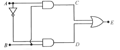
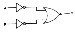
For the logic circuit shown, the truth table is
 A
A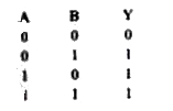 B
B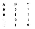 C
C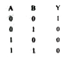 D
D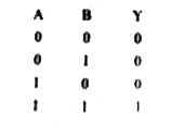
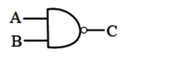
A logic gate and its truth table are shown below
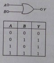
The gate is :ANORBANDCORDNOTA logic gate and its truth table are shown below

The gate is :ANORBANDCORDNOT


