In the circuit shown in figure (1), the V0,I1,ID1, and ID3 are respectively.
(A) 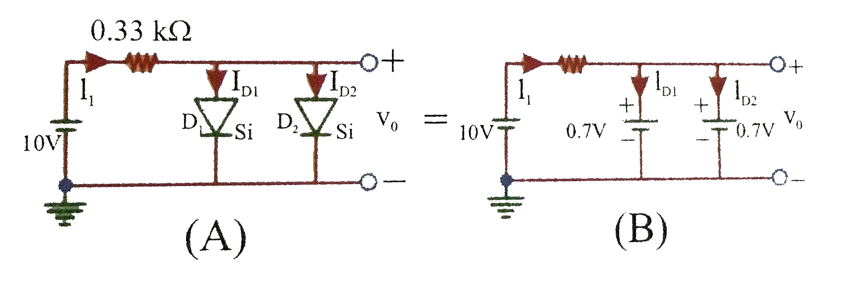
A
0.5V,25mA,15mA
B
0.7V,28.18mA,14.09mA
C
0.4V,15mA,20mA
D
0.3V,15.06mA,20.18mA
Video Solution
Text Solution
The correct Answer is:B
Since applied voltage is greater then 0.7 V and direction of current is same as direction of arrow head, both the diodes are in ..on.. state (see above figure(2)). Now V0 is parallel to D1andD2. Hence V0=0.7V
Current I1=VRR=E−VDR=10V−0.7V0.33kΩ
=28.18 mA
Both the silicon diodes have similar characteristics.
Hence ID1=ID2=I12=14.09mA
|
Updated on:21/07/2023
Topper's Solved these Questions
- BOOK - NARAYNACHAPTER - SEMICONDUCTOR ELECTRONICSEXERCISE - EXERCISE -2 (H.W) (APPLICATIONS OF JUNCTION DIODE AS RECTIFIER)4videos
SEMICONDUCTOR ELECTRONICS
- BOOK - NARAYNACHAPTER - SEMICONDUCTOR ELECTRONICSEXERCISE - EXERCISE -2 (H.W) (TRANSISTORS)9videos
SEMICONDUCTOR ELECTRONICS
- BOOK - NARAYNACHAPTER - SEMICONDUCTOR ELECTRONICSEXERCISE - EXERCISE -2 (H.W) (INTRINSIC, EXTRINSIC SEMICONDUCTORS)6videos
SEMICONDUCTOR ELECTRONICS
- BOOK - NARAYNACHAPTER - SEMI CONDUCTOR DEVICESEXERCISE - Level-II (H.W)36videos
SEMI CONDUCTOR DEVICES
- BOOK - NARAYNACHAPTER - WAVE OPTICSEXERCISE - Exercise - 4 Polarisation9videos
WAVE OPTICS
Similar Questions
Knowledge Check
- Question 1 - Select One
In the circuit shown in figure I1,I2 and ID2 are respectively-
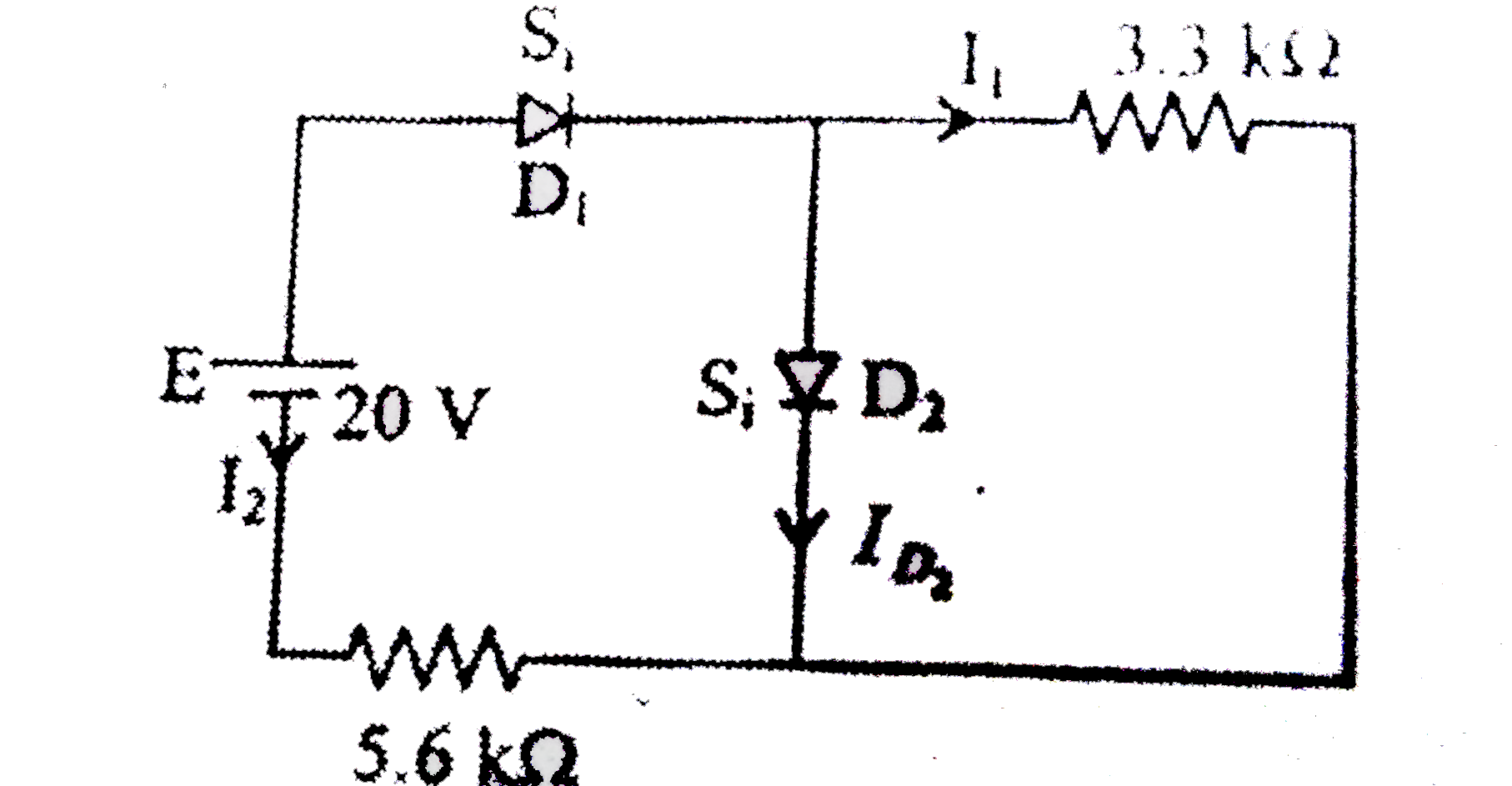 A0.212MA,3.32mA,3.108mAB2.12mA,3.32mA,3.108mAC0.212mA,0.332mA,3.108mADNone of these
 - Question 2 - Select One
In the circuit shown, the currents i1 and i2 are
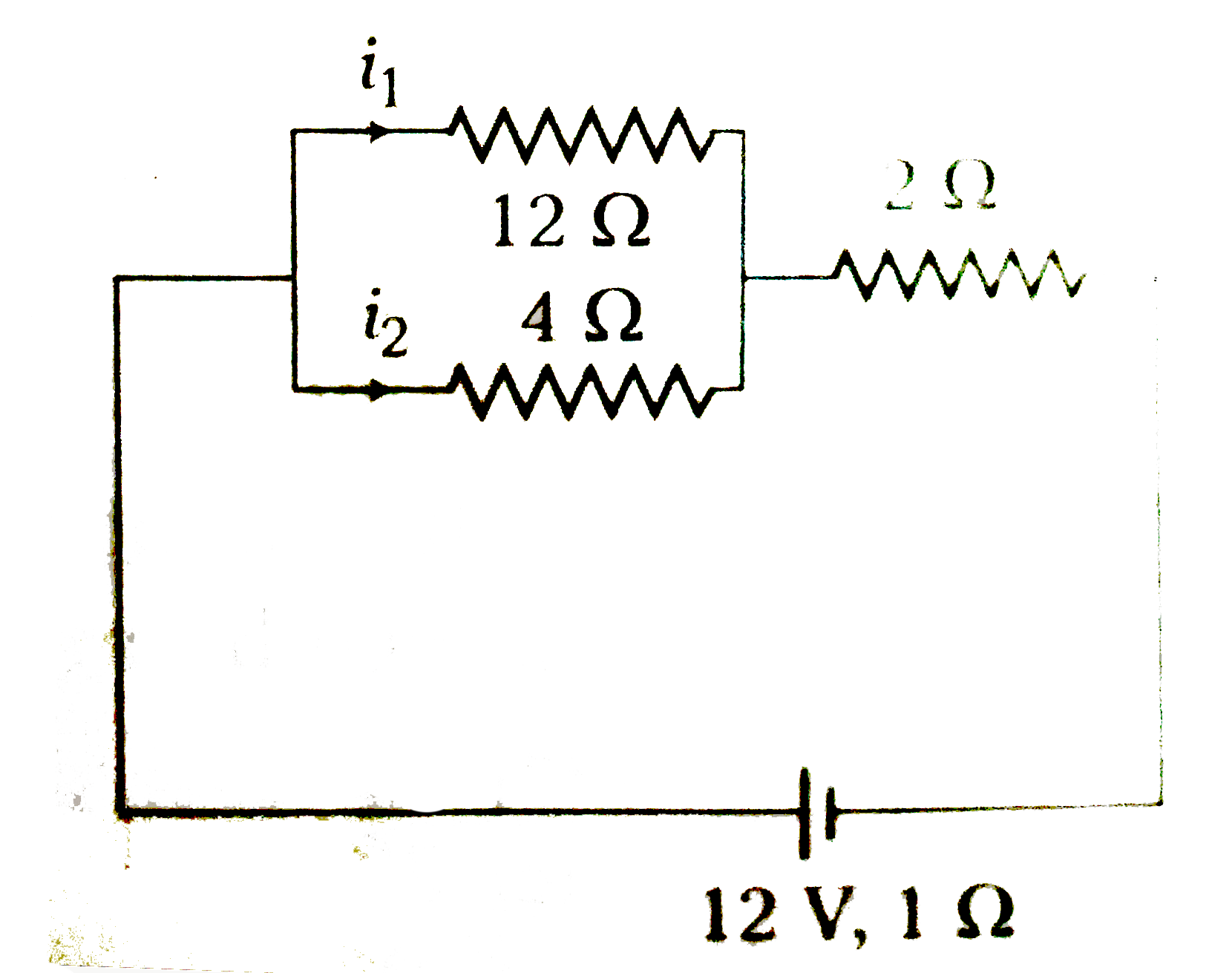 Ai1=1.5A,i2=0.5ABi1=0.5A,i2=1.5ACi1=1A.i2=3ADi1=3A,i2=1A
 - Question 3 - Select One
In the circuit shown, the value of currents I1,I2andI3 are
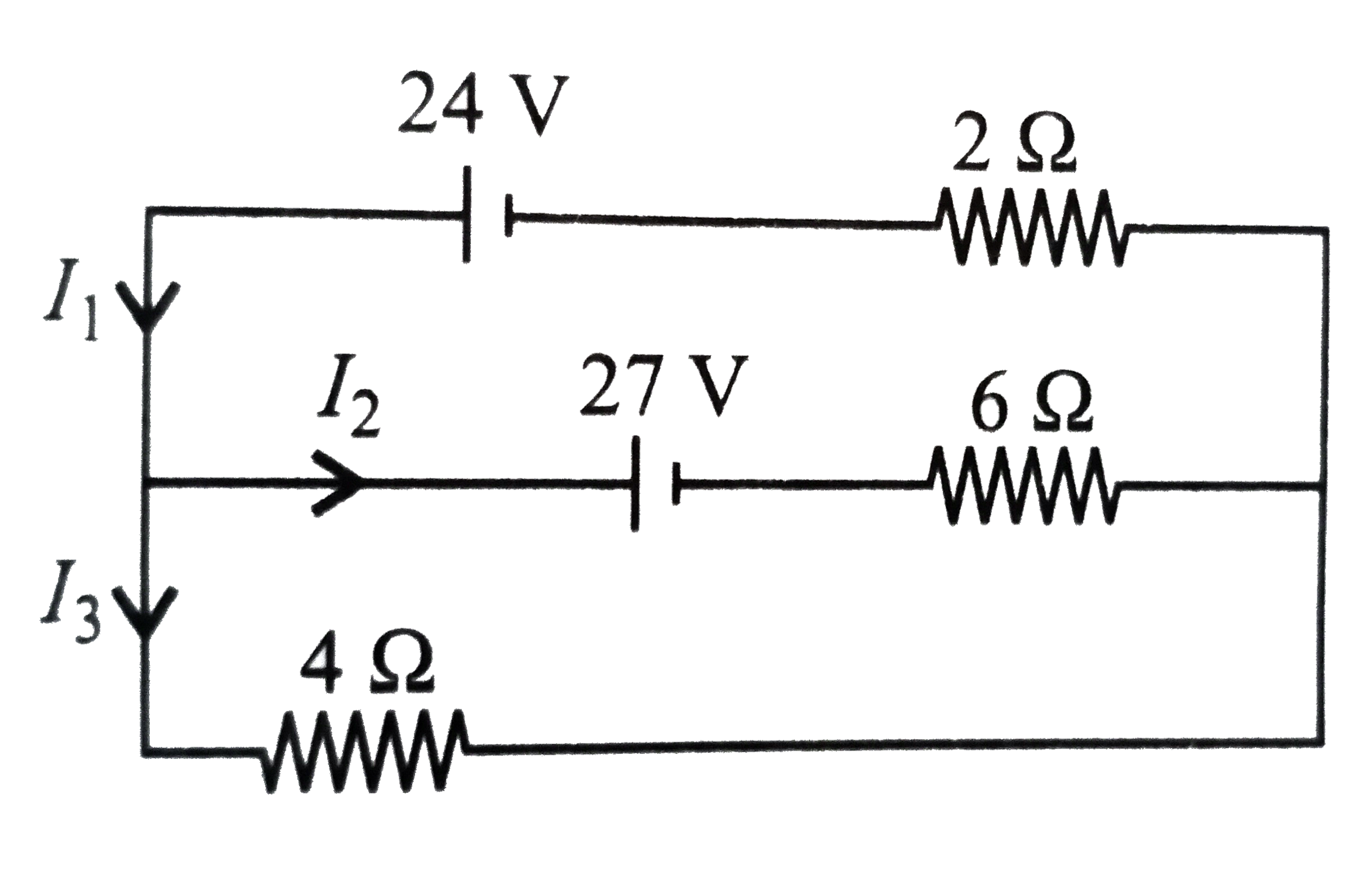 A3A,−3A2A,92AB92A,−32AC5A,4A,−3AD7A,54A,92A
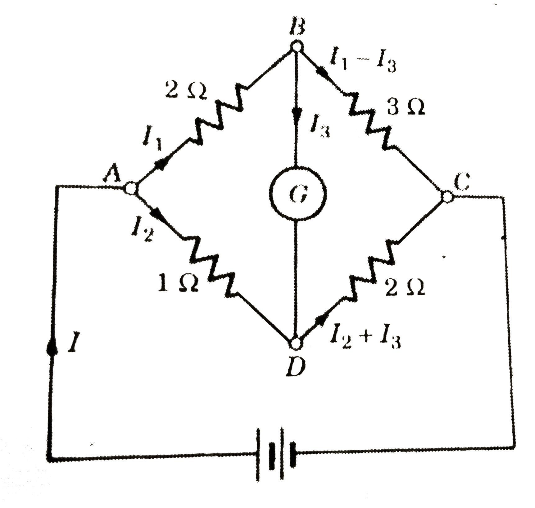
In the circuit shown in figure. Find the currents I,I1,I2andI3 given that emf of th battery=2V, internal resistance of the battery =2Ω and resistance of the galvanomter =4Ω.View SolutionIn the circuit shown in figure ,find the ratio of currents i1/i2.
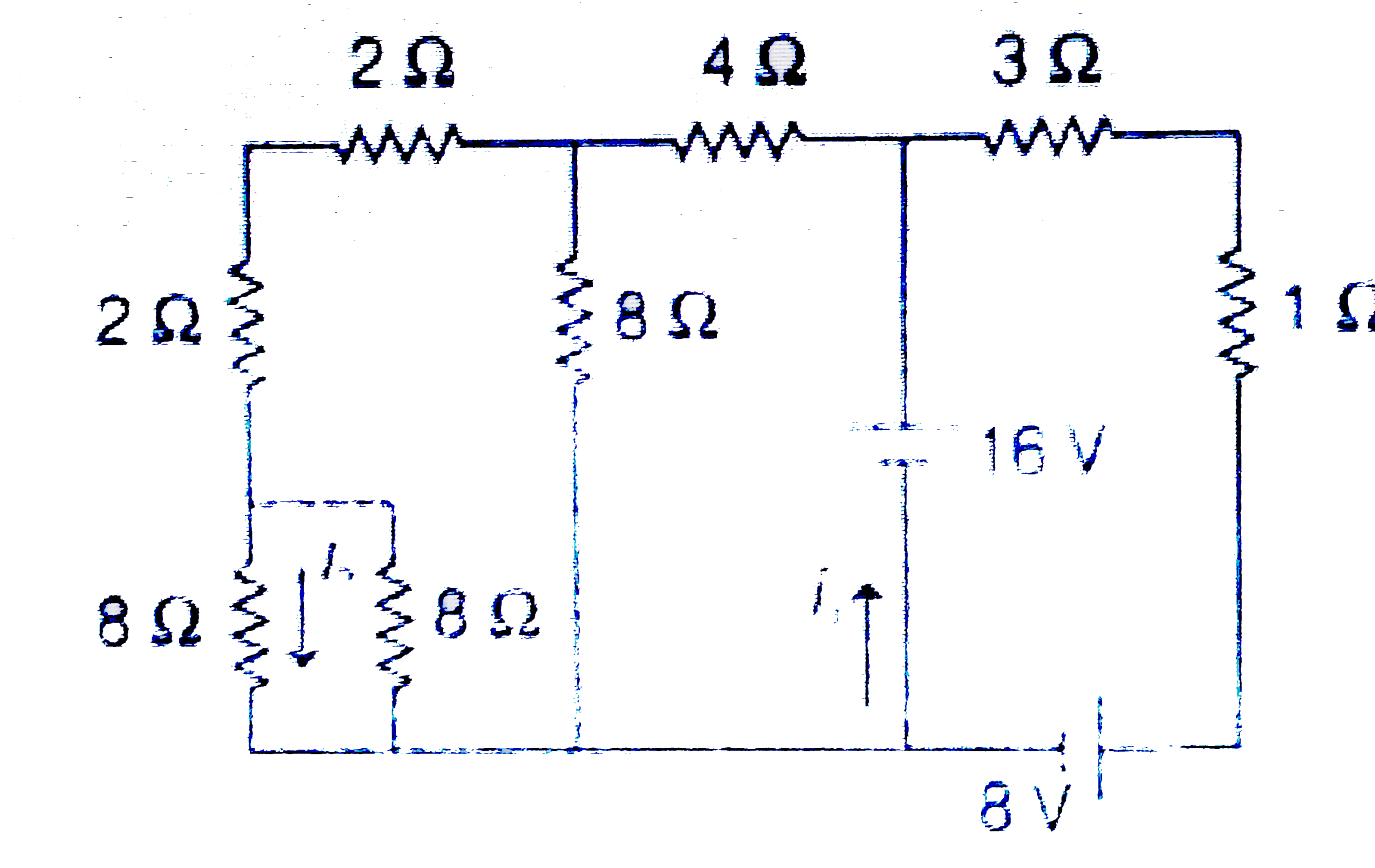 View Solution
In the circuit as shown in figure, the ratio of current i1/i2 is
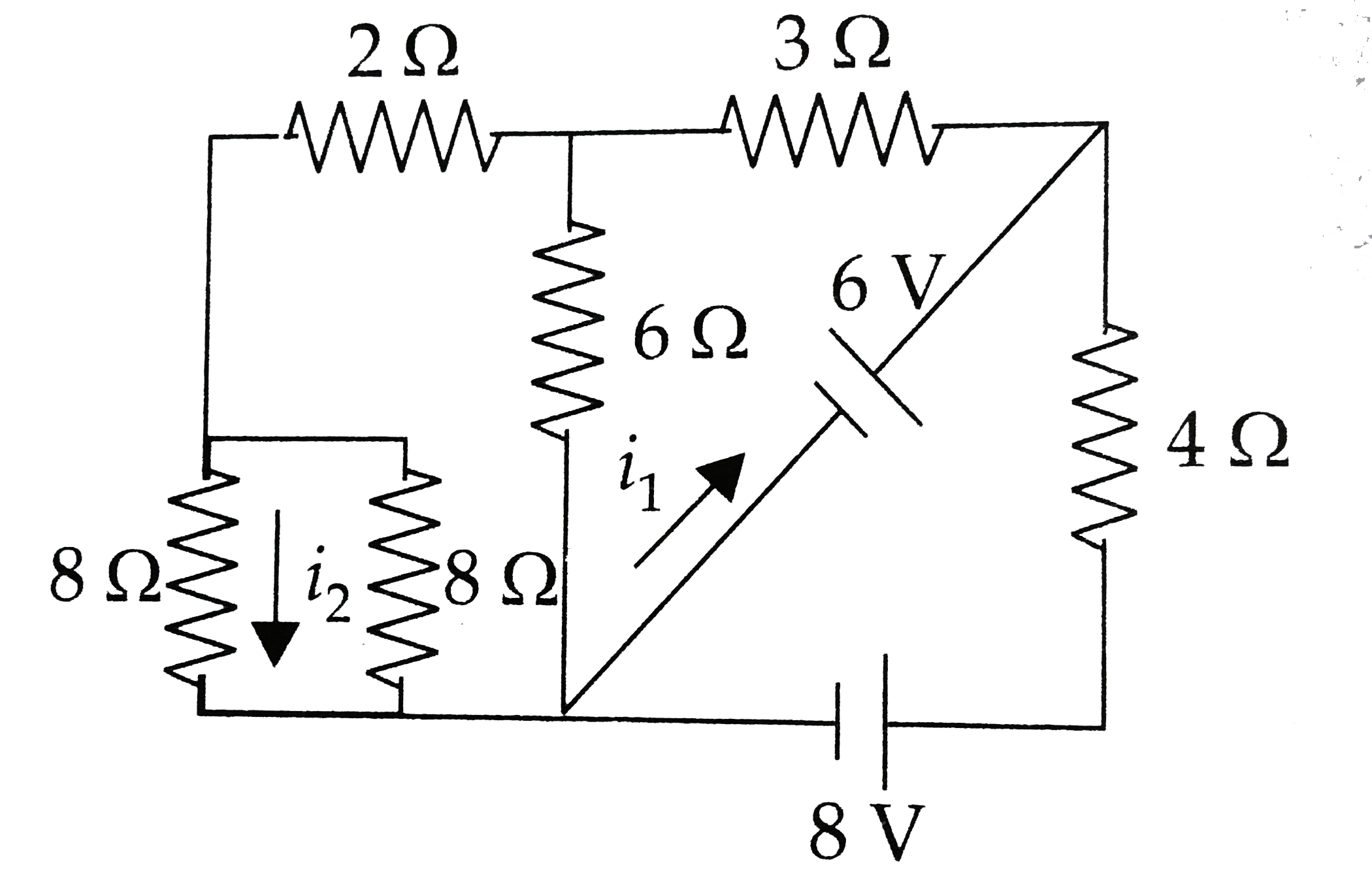 View Solution
In the circuit shown in the figure
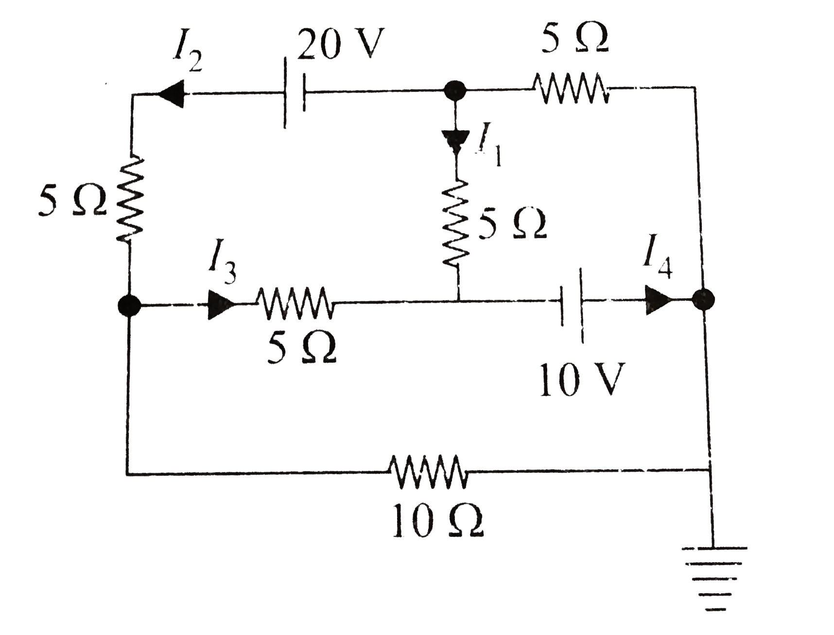 .
.
The value of current I1 isView SolutionIn the circuit shown, the switch is closed at t=0, the currents I1,I2 and I3 are
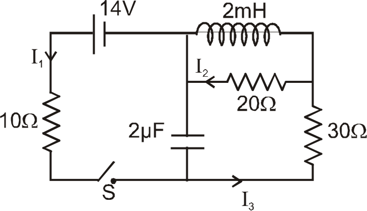 View Solution


