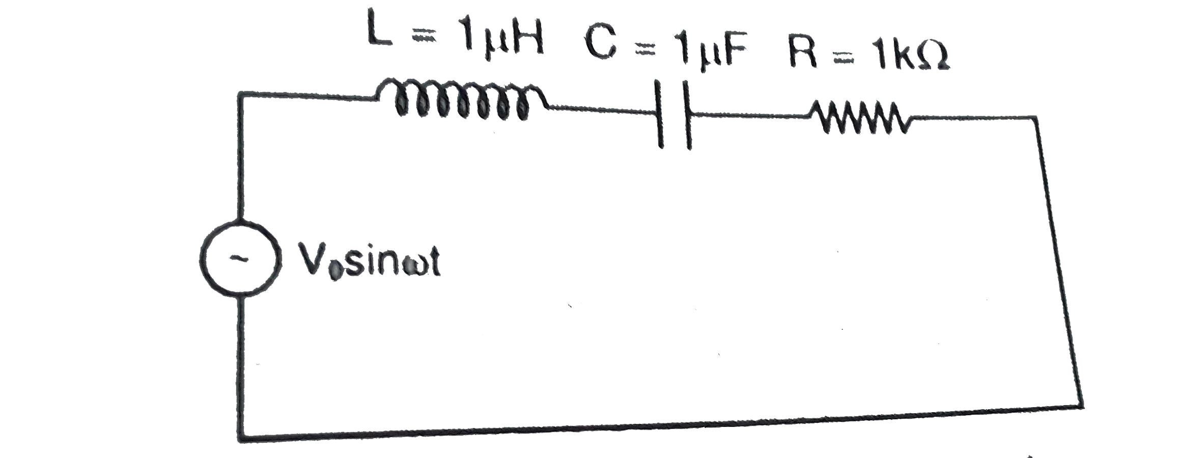
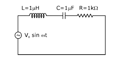
In the circuit shown, L=1μH,C=1μFandR=1kΩ. They are connected in series with an source V=V0sinωt as shown. Which of the following options is/are correct ?

The correct Answer is:C, D
Topper's Solved these Questions
- ALTERNATING CURRENTBOOK - RESONANCECHAPTER - ALTERNATING CURRENTEXERCISE - PART-II
6 Videos
- ALTERNATING CURRENTBOOK - RESONANCECHAPTER - ALTERNATING CURRENTEXERCISE - HIGH LEVEL PROBLEMS
11 Videos
- ALTERNATING CURRENTBOOK - RESONANCECHAPTER - ALTERNATING CURRENTEXERCISE - PART-IV Comprehension
11 Videos
- ATOMIC PHYSICSBOOK - RESONANCECHAPTER - ATOMIC PHYSICSEXERCISE - Advanved level problems
17 Videos
Similar Questions
In an L-R circuit, an inductance of 0.1 H and a resistance of 1Ω are connected in series with an ac source of voltage V = 5 sin 10 t. The phase difference between the current and applied voltage will be
View SolutionIn an L-R circuit, an inductance of 0.1 H and a resistance of 1Ω are connected in series with an ac source of voltage V = 5 sin 10 t. The phase difference between the current and applied voltage will be
View Solution
Knowledge Check
In the circuit shown, L=1μH,C=1μF and R=1kΩ. They are connected in series with an a.c. source V=V0sinωt as shown. Which of the following options is/are correct?
 AThe current will be in phase with the voltage if ω=104rad.s–1BAt ω>>106rad.s–1, the circuit behaves like a capacitorCThe frequency at which the current will be in phase with the voltage is independent of RDAt ω≅0 the current flowing through the circuit becomes nearly zero.
For a RLC series circuit , phasors of current i and applied voltage V=V0sinωt are shown in diagram at t=0, which of the following is/are CORRECT?
AAt =π2ω, instantaneous power supplied by source is negative.BFrom 0<t<2π3ω, average power supplied by source is positive.CAt t=5π6ω, instantaneous power supplied by source is negative.DIf ω is increased slightly, angle between the two phasors decreases.In a series LCR circuit with an AC source (Erms50Vandv=50/πHz),R=300Ω,C=0.02mF,L=1.0H , which of the following is correct
Athe rms current in the circuit is 0.1 ABthe rms potential difference across the capacitor is 50 VCthe rms potential difference across the capacitor is 14.1 VDthe rms current in the circuit is 0.14 A
In a series LCR circuit with an AC source (Erms50Vandv=50/πHz),R=300Ω,C=0.02mF,L=1.0H , which of the following is correct
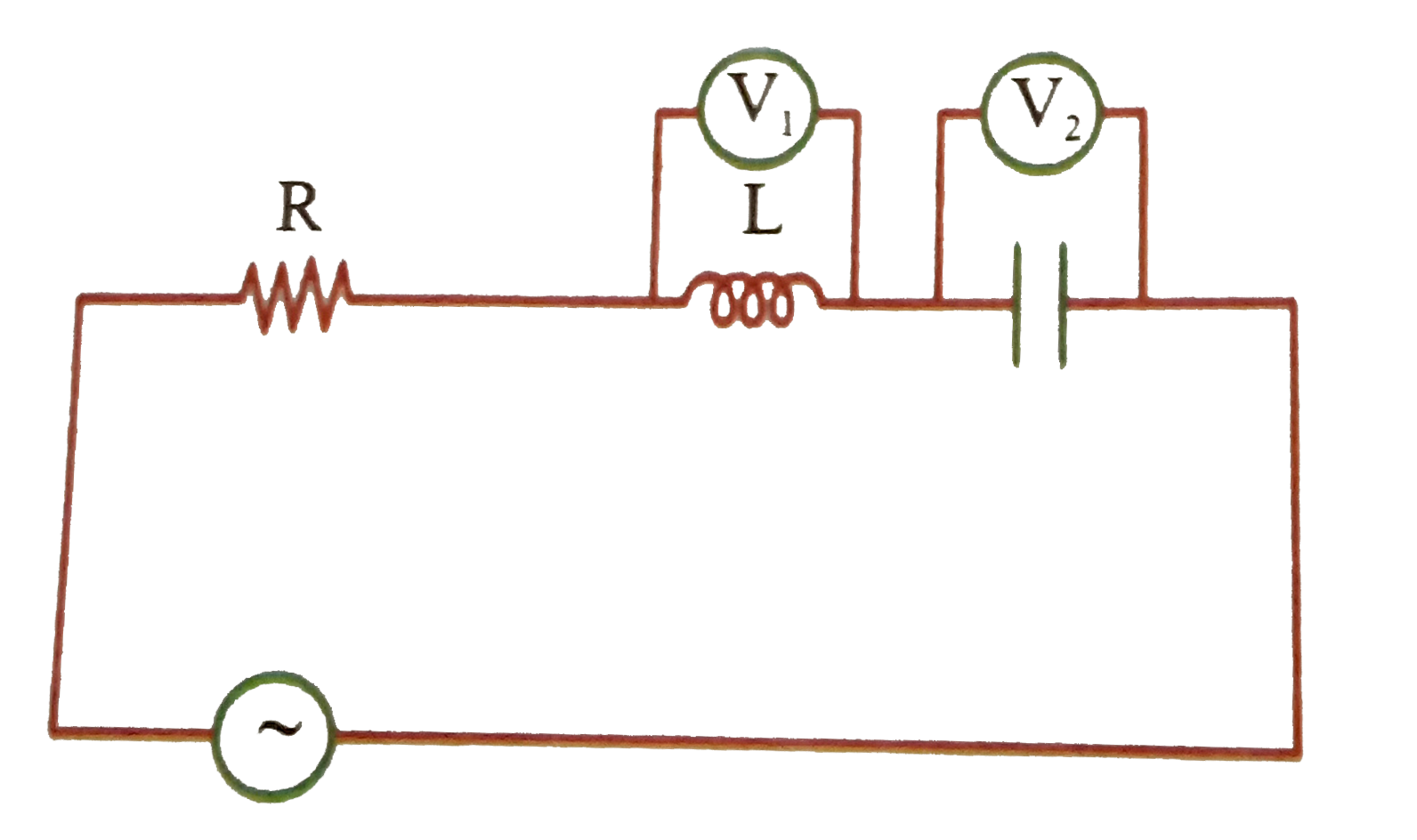
View SolutionIn the figure shown R=100Ω, L=2πH and C=8πμF are connected in series with a.c source of 200 volt and frequency 'f'. V1 and V2 are two hot-wire voltmeters. If the readings of V1 and V2 are same then:

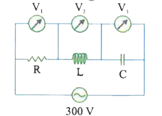
View SolutionThe figure shows a LCR netework connected to 300V ac supply. The circuit elements are such that R=XL=XC=10Ω V1,V2 and V3 are three ac voltmeters connected as shown in the figure. Which of the following represents the correct set of readings of the voltmeters ?

View SolutionThe figure shows a LCR netework connected to 300V ac supply. The circuit elements are such that R=XL=XC=10Ω V1,V2 and V3 are three ac voltmeters connected as shown in the figure. Which of the following represents the correct set of readings of the voltmeters ?

View SolutionIn the figure shown R=100ΩL=2πH and C=8πμF are connected in series with a.c source of 200 volt and frequency 'f'. V1 and V2 are two hot-wire voltmeters. If the readings of V1 and V2 are same then:

View Solution
