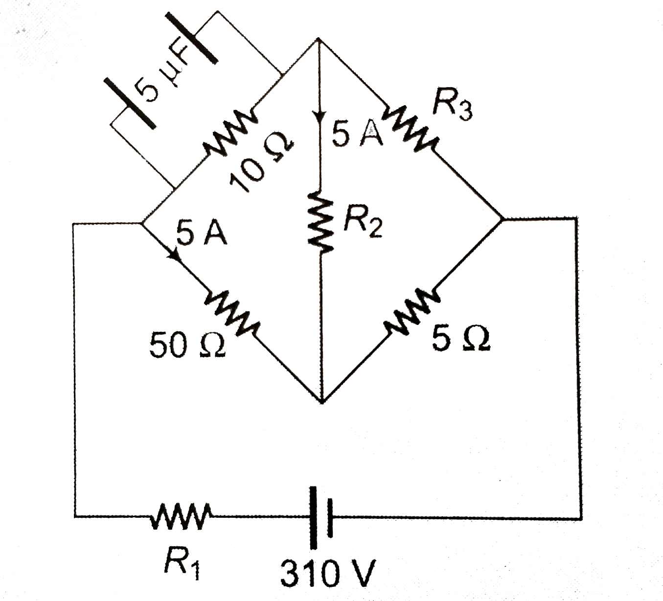
If the charge on the capacitor is 1 mC in the given circuit,
then R1R2R3=.....Ω .
A
6
B
0.4
C
0.6
D
10
Text Solution
The correct Answer is:C
Charge on cap = 1 mC
Vcapacitro=QC=1×10−35×10−6=10005
= 200 V
So, current throught R5
I=VR
=20010
20 A
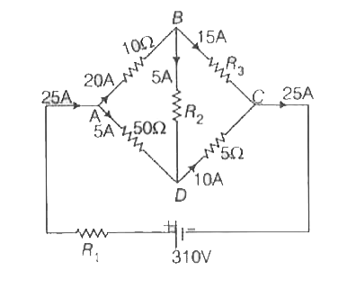
Hence, we have following current distribution .
In loop BCDB,
−15R3+10×5+5R2=0 ...(i)
In loop ABCDA,
−200−15R3+50+250=0
15R3=100
R3=10015Ω
From Eq. (i), we get
5R2=50
R2=10Ω
and from loop ADCA,
−250−50n+310−25R1=0
25R1=10
⇒R1=1025Ω
So, R1×R2R3=1025×10(10015)
=1525=35=0.6
|
Topper's Solved these Questions
- AP EAMCET ENGINEERING ENTRANCE EXAM ONLINE QUESTION PAPER 2019 (SOLVED)BOOK - TS EAMCET PREVIOUS YEAR PAPERSCHAPTER - AP EAMCET ENGINEERING ENTRANCE EXAM ONLINE QUESTION PAPER 2019 (SOLVED)EXERCISE - PHYSICS
39 Videos
- AP EAMCET SOLVED PAPER 2018 ( 23-04-2019,SHIFT -1)BOOK - TS EAMCET PREVIOUS YEAR PAPERSCHAPTER - AP EAMCET SOLVED PAPER 2018 ( 23-04-2019,SHIFT -1)EXERCISE - Physics
40 Videos
Similar Questions
Knowledge Check
In the circuit shown in the given figure, the resistances R1andR2 are respectively
 A14Ωand40ΩB40Ωand44ΩC40Ωand30ΩD14Ωand30Ω
In the given circuit, R1 = 10Ω R2=6Omega and E = 10V, then correct statement is
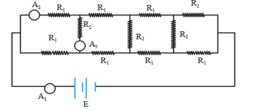 AEffective resistance of the circuit is 10ΩBR Reading of A1 is 1//2 amp.CReading of A2 is 1//2 ampDReading of A3 is 1//8 amp.
Find the time constant (in μs) for the given RC circuits in the given order respectively.
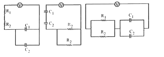
R1=1ω,R2=2ω,C1=4μF,C2=2μFA18,4,89B18,89,4C4,18,89D4,89,18
In the given circuit, R1 = 10Ω R2=6Ω and E = 10V, then correct statement is

View SolutionDetermine the voltage drop across the resistance R1 in the circuit given in Fig. 4.55 with ε=90V,R1=5kΩ,R2=5kΩ,R3=10kΩ and R4=10kΩ.
View SolutionDetermine the voltage drop across the resistor R1 in the circuit given below with E = 65V, R_1 = 50 OmegaR_2 = 100 Omega, R_3 = 100 Omega, and R_4 300 Omega.
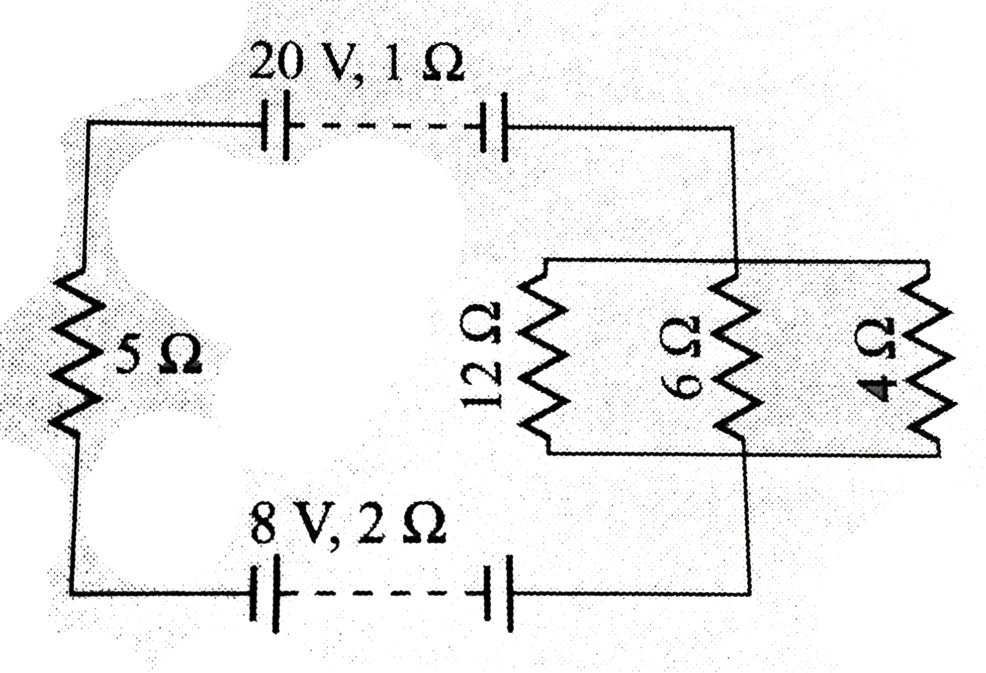
View SolutionR-C Circuit||Charging of Capacitor
View SolutionThe charge across the capacitor in two different RC circuit 1 and 2 are potted as shown in figure.
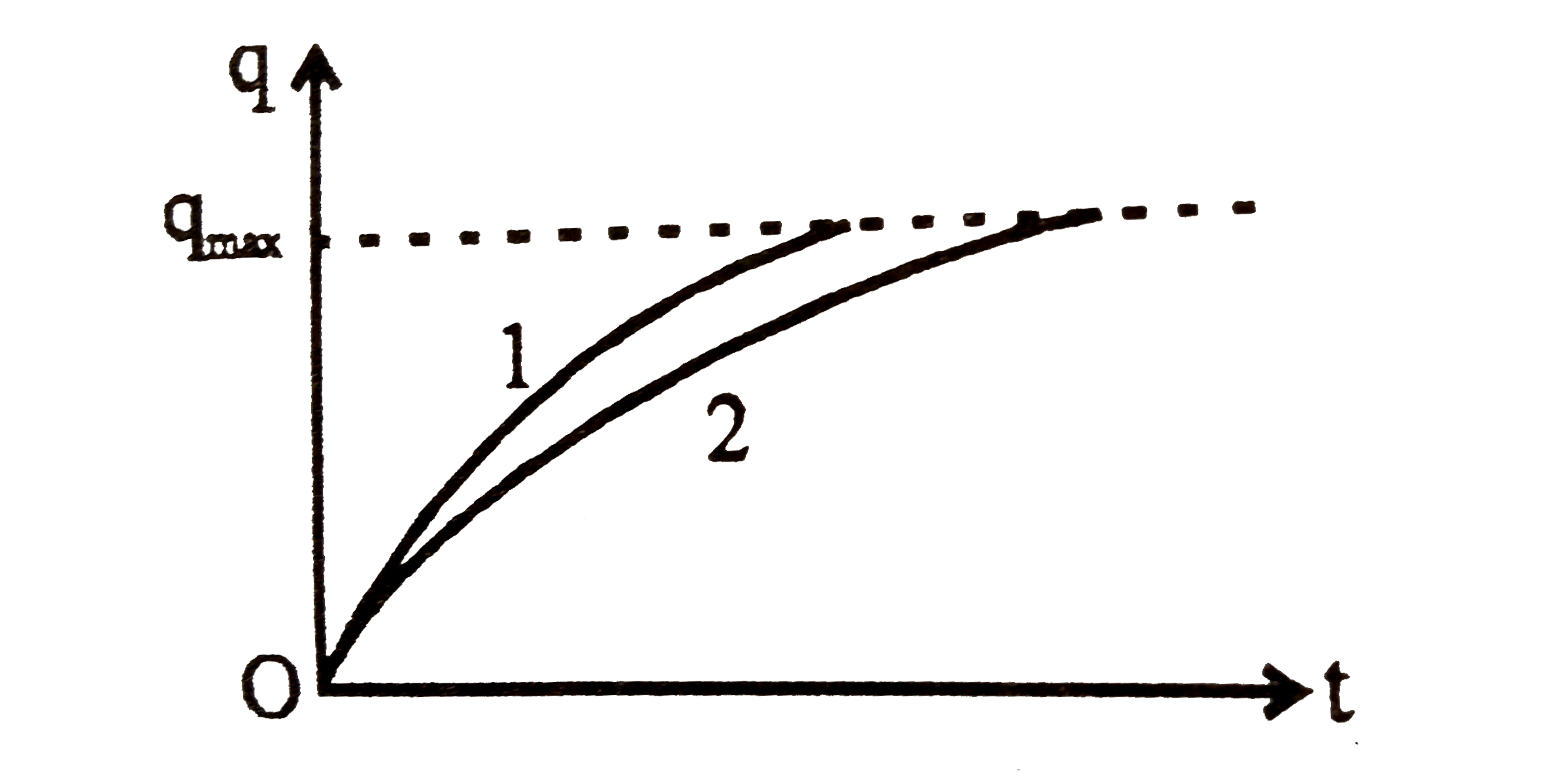
Identify the correct statement (s) related to the R1,R2,C1 and C2 of the two RC circuit-
View Solution

