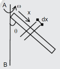
A thin rod AB is kept in a region of uniform magnetic field outward directed as shown in the figure.
 Rod is made to rotate about the pivoted end A with angular velocity ω. Calculate potential difference generated between the two ends of the rod.
We know that when a rod moves perpendicular to magnetic field and perpendicular to its length then motional emf generated between its two ends is given by Bul, where symbols have usual meaning. In this given situation, due to rotation the rod has different velocities for different points and hence we cannot use the formula directly. We can select a segment of length dx at a distance x from the pivot. Then speed for this segment of rod may be assumed as constant and equal to xω. We can now use formula of motional emf for this segment. Potential difference generated across the segment of the rod can be written as follows:
dV=B(xω)dx
On integrating it for the entire length of the rod we can get total potential difference appearing between two ends A and B of the rod.
V=∫dV=∫10B(xω)dx
⇒V=Bω∫10xdx
⇒V=Bω[x22]10
⇒V=12Bωl2
Topper's Solved these Questions
- ELECTROMAGNETIC INDUCTIONBOOK - MODERN PUBLICATIONCHAPTER - ELECTROMAGNETIC INDUCTIONEXERCISE - PRACTICE PROBLEMS
25 Videos
- ELECTROMAGNETIC INDUCTIONBOOK - MODERN PUBLICATIONCHAPTER - ELECTROMAGNETIC INDUCTIONEXERCISE - CONCEPTUAL QUESTIONS
22 Videos
- ELECTRIC CHARGES AND FIELDS BOOK - MODERN PUBLICATIONCHAPTER - ELECTRIC CHARGES AND FIELDS EXERCISE - Chapter Practice Test
15 Videos
- ELECTROMAGNETIC WAVESBOOK - MODERN PUBLICATIONCHAPTER - ELECTROMAGNETIC WAVESEXERCISE - CHAPTER PRACTICE TEST
14 Videos
Similar Questions
Knowledge Check
A rod is rotating with angular velocity ω about axis AB. Find cosθ.
 Ag2lω2Bglω2C2g(lω)2D3g2lω2
A copper rod of length l is rotated about one end perpendicular to the uniform magnetic field B with constant angular velocity ω . The induced e.m.f. between its two ends is
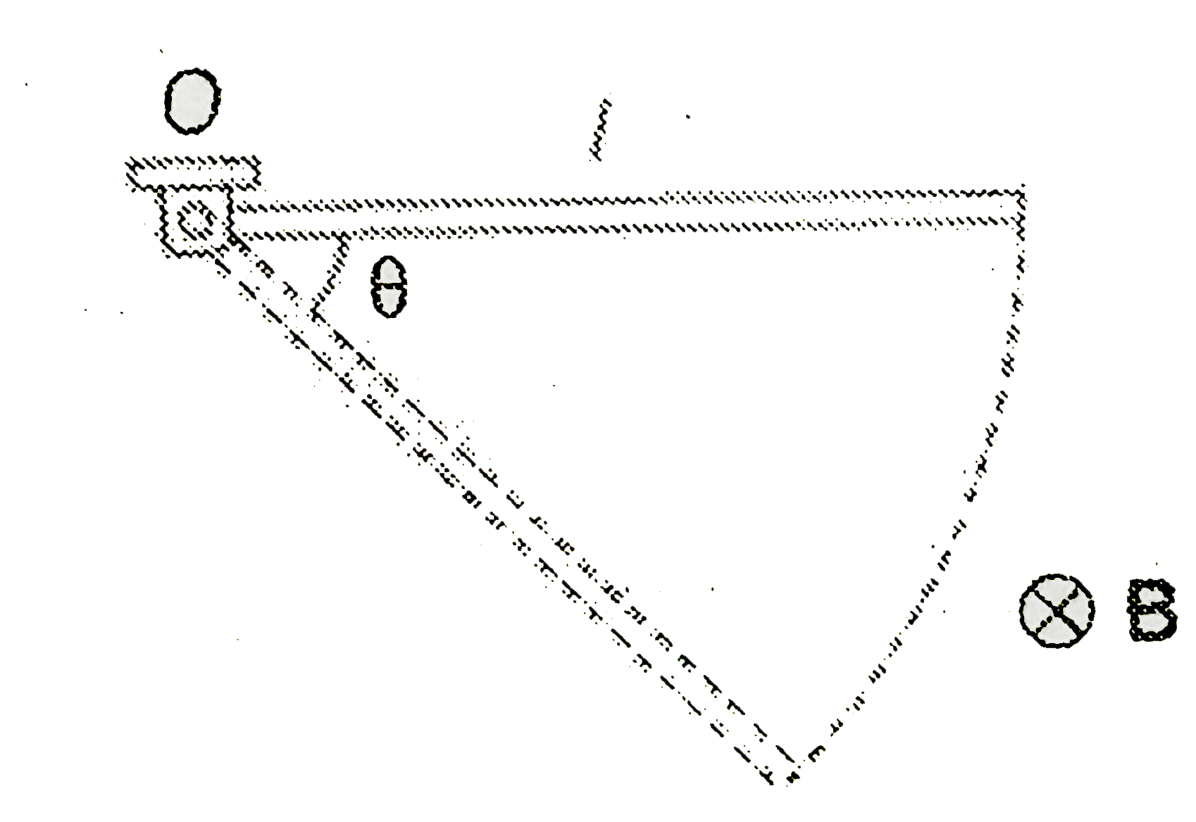
A12Bωl2B34Bωl2CBωl2D2Bωl2A conducting rod of length l is higed at point O. It is free to rotate in a vertical plane. There exists a uniform magnetic field →B in horizontal direction. The rod is released from the position shown in figure. Potential difference between the two ends of the rod is proportional to
Al3/2Bl2CsinθD(sinθ)1/2
A thin rod of copper is being moved in a uniform magnetic field such that it is cutting the magnetic field lines. An emf is induced between the ends of the rod.
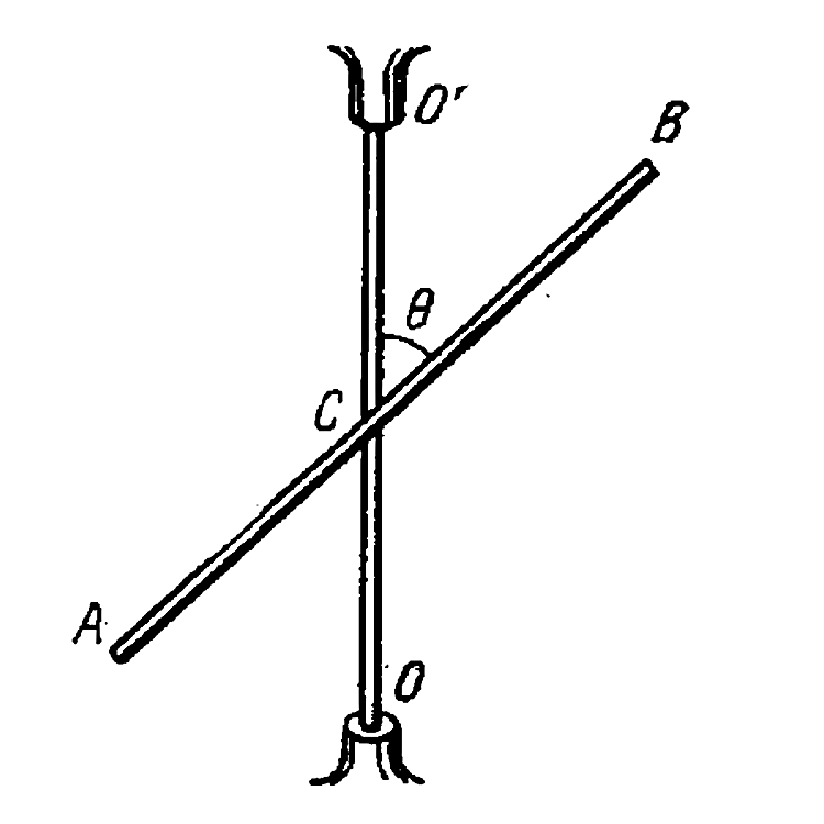
View SolutionA midpoint of a thin uniform rod AB of mass m and length l is rigidly fixed to a rotation axle OO′ as shown in figure. The rod is set into rotation with a constant angular velocity ω. Find the resultant moment of the centrifugal forces of inertia relative to the point C in the reference frame fixed to the axle OO′ and to the end.

View SolutionA conducting rod of length l is hinged at point O. It is a free to rotate in a verical plane. There exists a uniform magnetic field B in horizontal direction. The rod is released from the position shown. The potential difference between the two ends of the rod is proportional to

View Solutionif rod is rotated about an axis passing through its mid-point , the potential difference between the ends of rod is
View SolutionA conducting rod of length l is hinged at point O. It is a free to rotate in a verical plane. There exists a uniform magnetic field B in horizontal direction. The rod is released from the position shown. The potential difference between the two ends of the rod is proportional to

View Solution
