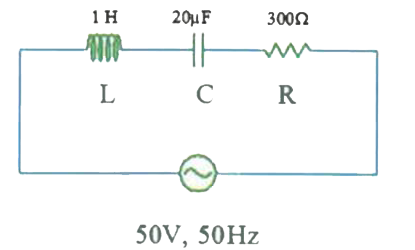
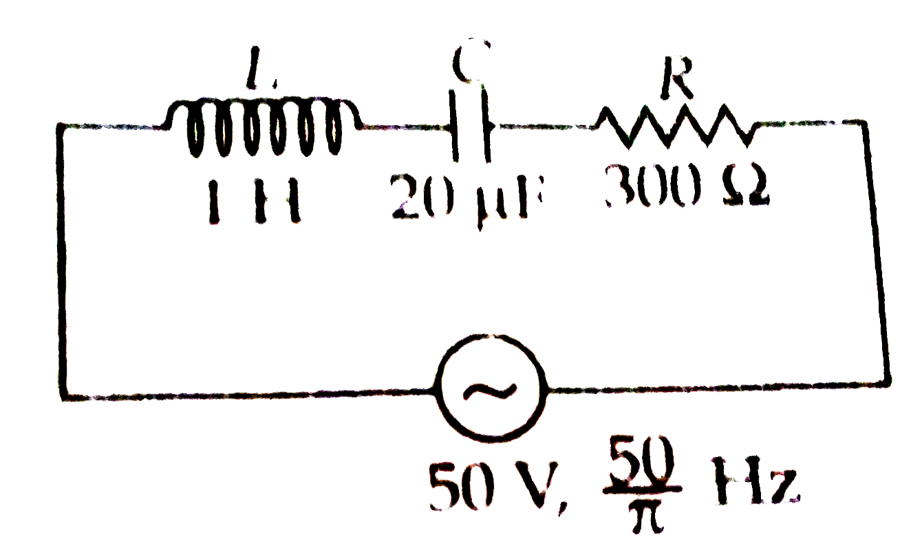
In a series LCR circuit, how can we achieve the maximum power by choosing appropriate value of capacitance of the capacitor in the circuit ?
To achieve maximum power in a series LCR (Inductor-Capacitor-Resistor) circuit by choosing an appropriate value of capacitance, follow these steps:
1. Understand the Power Formula: The power drawn from the source in an LCR circuit is given by the formula:
P=Vrms⋅Irms⋅cosϕ
where ϕ is the phase angle between the voltage and the current.
2. Identify the Role of Power Factor: The term cosϕ is known as the power factor. To achieve maximum power, we need to maximize cosϕ.
3. Relate Power Factor to Impedance: The power factor cosϕ can be expressed in terms of resistance R and impedance Z:
cosϕ=RZ
where Z is the total impedance of the circuit.
4. Determine Impedance in LCR Circuit: In a series LCR circuit, the total impedance Z is given by:
Z=√R2+(XL−XC)2
where XL is the inductive reactance and XC is the capacitive reactance.
5. Condition for Maximum Power: For maximum power, we want cosϕ to be equal to 1. This occurs when the phase angle ϕ is 0 degrees, meaning:
XL−XC=0
or equivalently,
XL=XC
6. Express Reactance in Terms of Capacitance: The inductive reactance XL is given by:
XL=ωL
and the capacitive reactance XC is given by:
XC=1ωC
where ω is the angular frequency of the AC source.
7. Set Inductive and Capacitive Reactance Equal: To achieve resonance (maximum power), set XL equal to XC:
ωL=1ωC
8. Solve for Capacitance: Rearranging the equation gives:
C=1ω2L
This equation shows how to choose the capacitance C to achieve maximum power in the circuit.
Conclusion:
To achieve maximum power in a series LCR circuit, select the capacitance C such that the capacitive reactance equals the inductive reactance, which can be calculated using the formula C=1ω2L.
P=Vrms⋅Irms⋅cosϕ
where ϕ is the phase angle between the voltage and the current.
cosϕ=RZ
where Z is the total impedance of the circuit.
Z=√R2+(XL−XC)2
where XL is the inductive reactance and XC is the capacitive reactance.
XL−XC=0
or equivalently,
XL=XC
XL=ωL
and the capacitive reactance XC is given by:
XC=1ωC
where ω is the angular frequency of the AC source.
ωL=1ωC
C=1ω2L
This equation shows how to choose the capacitance C to achieve maximum power in the circuit.
To achieve maximum power in a series LCR circuit, select the capacitance C such that the capacitive reactance equals the inductive reactance, which can be calculated using the formula C=1ω2L.
Topper's Solved these Questions
- ALTERNATING CURRENT BOOK - MODERN PUBLICATIONCHAPTER - ALTERNATING CURRENT EXERCISE - TOUGH & TRICKY PROBLEMS
12 Videos
- ALTERNATING CURRENT BOOK - MODERN PUBLICATIONCHAPTER - ALTERNATING CURRENT EXERCISE - NCERT FILE (TEXTBOOK EXERCISES )
11 Videos
- ALTERNATING CURRENT BOOK - MODERN PUBLICATIONCHAPTER - ALTERNATING CURRENT EXERCISE - PRACTICE PROBLEMS
67 Videos
- ATOMS BOOK - MODERN PUBLICATIONCHAPTER - ATOMS EXERCISE - Chapter Practice Test
16 Videos
Similar Questions
Knowledge Check
In a series LCR circuit, at resonance the
Atotal inpedance is Lω−(1/Cω)Btoal impedance is RCvoltage across C and L are in phaseDthe voltage across C lags the source voltage by π/2In series LCR circuit at resonance,
Acurrent is maximum and impedance is maximumBcurrent is maximum and impedance is minimumCcurrent is minimum and impedance is maximumDcurrent is minimum and pmpedance is minimumIn series LCR circuit at resonance,
Acurrent is maximum and voltage is minimumBcurrent is maximum and voltage is maximumCcurrent is minimum and voltage is maximumDcurrent is minimum and voltage is minimum


