Discuss common-base configuration in amplifier using n-p-n transistor. Calculate its current gain and voltage gain.
Concept of an amplifier. It is a device by which we can increase the amplitude of variation of alternating voltage and current.
Circuit for n-p-n common base amlifier is as shown in the diagram. Forward biasing is applied to E-B and reverse biasing is applied to B-C circuit. Input is fed at a and b while ouput is taken from c and d.

Working and amplification action. When input a.c. signal is zero and emitter base circuit is closed, the currents Ie, Ib and Ic flow as the emitter, base and collector current.
From Kirchhoff.s first law ,
Ie=Ib+Ic
If Ib=5%, Ie=0.05Ie and Ic=0.95Ie
The collector voltage Vc is given by
Vc=Vcb−IcRL............(i)
When signal is fed to E−B circuit, there is a change in forward bias resulting in change of Ie, Ic and consequenctly, Vc which appears as amplified output.
Phase relationship between input and output voltage. When positive half of signal (a.c.) is fed to E-B circuit, it decreases forward bias which in turn decreases Ie and Ic.
Decrease in Ic means an increase of Vc [Eq. (i)]. Thus during positive half cycle of input a.c. signal voltage, the output signal voltage at collector also varies through positive half cycle.
When negative half cycle of input a.c. signal voltage is fed, it supports forward biasing of the emitter base circuit. The results in increase in Ie and hence Ic. From equation (i), Vc decreases i.e. it becomes lesser positive or more negative.
Thus during negative half cycle of input a.c.signal voltage the output signal voltage at the collector also varies through negative half of the cycle.
Thus in common base amlifier output is in phase with input.
Advantage of common base amplifier over common emitter amplifier. The only advantgae of common base or common emitter is that input and output are in phase otherwise in all other respects common emitter amplifier is preferred.
Current aimplification factor (or current gain) a is defined as the ratio of collector current to the emitter current at constant collector voltage.
i.e. a=(IcIe)Ecb
Voltage gain (Av). The ratio of change of output voltage to the change in input voltage is called voltage gain. Hence
Av=ΔV0ΔVi=IcRLIeRi=αRLRi
So Av=α (Resistance gain)
Since RL>>Ri so Av is quite high although α<1. to the change in input power is called power gain.
P=ΔP0ΔPi=IcΔV0IeΔvi=αAv
Topper's Solved these Questions
- SOLIDS AND SEMICONDUCTOR DEVICESBOOK - MBD -HARYANA BOARDCHAPTER - SOLIDS AND SEMICONDUCTOR DEVICESEXERCISE - Long answer type questions
6 Videos
- SOLIDS AND SEMICONDUCTOR DEVICESBOOK - MBD -HARYANA BOARDCHAPTER - SOLIDS AND SEMICONDUCTOR DEVICESEXERCISE - Objective type questions
21 Videos
- SOLIDS AND SEMICONDUCTOR DEVICESBOOK - MBD -HARYANA BOARDCHAPTER - SOLIDS AND SEMICONDUCTOR DEVICESEXERCISE - Objective type questions
21 Videos
- PRINCIPLES OF COMMUNICATIONBOOK - MBD -HARYANA BOARDCHAPTER - PRINCIPLES OF COMMUNICATIONEXERCISE - Objective Type Questions
19 Videos
Similar Questions
Knowledge Check
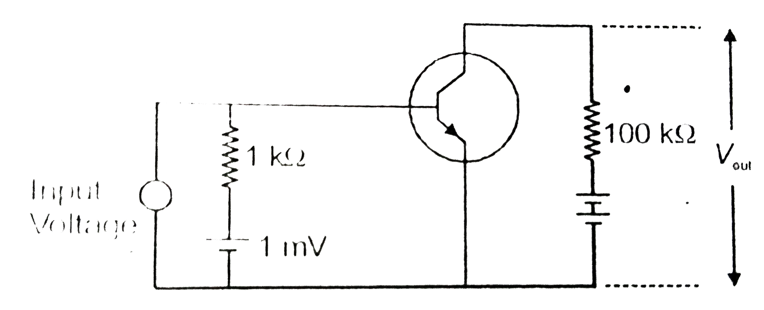
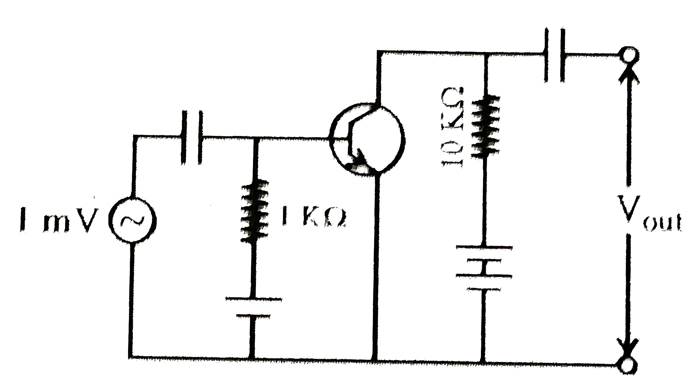
In the following common emitter configuration, and n-p-n transistor with current gain β=100 is used. The output voltage of the amplifier will be
 A10 mVB0.1 VC1.0 VD10 V
For a transistor is common base configuration if β is 100 , the value of current gain is is
A1B0.99C0.1D0.01For transistor amplifier, the voltage gain
Aremains constant for all frequenciesBis high and low frequencies and constant in the middle frequency rangeCis low at high and low frequencies and constant in the mid frequenciesDNone of the above.
In the following common emitter configuration an n-p-n transistor with current gain β=100 is used. What is the output voltage of the amplifier ?

View SolutionIn the following common emitter configuration an n-p-n transistor with current gain β=100 is used. What is the output voltage of the amplifier ?

View SolutionDraw a labelled circuit diagram of a common base amplifier using a p-n-p transistor. Define the term voltage gain and write an expression for it.
View SolutionDraw a labelled circuit diagram of n - p - n germanium transistor in common emitter configuration. Explain briefly, how this transistor is used as a voltage amplifier.
View SolutionGive a circuit diagram of a common emitter amplifier using an n-p-n transistor. Draw the input and output wavefroms of the signal. Write the expression for its voltage gain.
View Solution

