Write the ray diagram for formation of image in the simple microscope.
To draw the ray diagram for the formation of an image in a simple microscope (which is essentially a convex lens), follow these steps:
1. Identify the Lens and Object Position:
- Draw a convex lens vertically in the center of your diagram. Label the focal points on both sides as F1 and F2.
- Place the object (represented as an arrow) on the left side of the lens, ensuring it is positioned between the lens and the focal point (i.e., at a distance less than the focal length, f).
2. Draw the Principal Axis:
- Draw a horizontal line through the center of the lens. This line is called the principal axis.
3. Draw the First Ray:
- From the top of the object, draw a ray parallel to the principal axis towards the lens. When this ray hits the lens, it will refract through the focal point on the opposite side (F2).
4. Draw the Second Ray:
- From the top of the object, draw a second ray that passes through the center (or pole) of the lens. This ray will continue in a straight line without bending.
5. Locate the Image:
- Extend both refracted rays backward (on the same side as the object). The point where these two extended rays meet is where the image is formed. This point will be virtual since the rays diverge.
6. Label the Image:
- Draw an arrow from the principal axis to the point where the rays meet, indicating the height of the image (HI). This image will be upright and larger than the object (HO).
7. Indicate the Characteristics:
- Note that the image is virtual, upright, and magnified compared to the object.
Final Diagram:
- Your final diagram should show the convex lens, the object, the two rays (one parallel and one through the center), and the virtual image formed on the same side as the object.
---
- Draw a convex lens vertically in the center of your diagram. Label the focal points on both sides as F1 and F2.
- Place the object (represented as an arrow) on the left side of the lens, ensuring it is positioned between the lens and the focal point (i.e., at a distance less than the focal length, f).
- Draw a horizontal line through the center of the lens. This line is called the principal axis.
- From the top of the object, draw a ray parallel to the principal axis towards the lens. When this ray hits the lens, it will refract through the focal point on the opposite side (F2).
- From the top of the object, draw a second ray that passes through the center (or pole) of the lens. This ray will continue in a straight line without bending.
- Extend both refracted rays backward (on the same side as the object). The point where these two extended rays meet is where the image is formed. This point will be virtual since the rays diverge.
- Draw an arrow from the principal axis to the point where the rays meet, indicating the height of the image (HI). This image will be upright and larger than the object (HO).
- Note that the image is virtual, upright, and magnified compared to the object.
- Your final diagram should show the convex lens, the object, the two rays (one parallel and one through the center), and the virtual image formed on the same side as the object.
Topper's Solved these Questions
- RAY OPTICS AND OPTICAL INSTRUMENTSBOOK - MODERN PUBLICATIONCHAPTER - RAY OPTICS AND OPTICAL INSTRUMENTSEXERCISE - Revision Exercises (Additional Questions)
22 Videos
- RAY OPTICS AND OPTICAL INSTRUMENTSBOOK - MODERN PUBLICATIONCHAPTER - RAY OPTICS AND OPTICAL INSTRUMENTSEXERCISE - Revision Exercises (Fill in the Blanks)
10 Videos
- RAY OPTICS AND OPTICAL INSTRUMENTSBOOK - MODERN PUBLICATIONCHAPTER - RAY OPTICS AND OPTICAL INSTRUMENTSEXERCISE - Higher Order Thinking Skills & Advanced Level (QUESTIONS WITH ANSWERS)
20 Videos
- NUCLEIBOOK - MODERN PUBLICATIONCHAPTER - NUCLEIEXERCISE - CHAPTER PRACTICE TEST FOR BOARD EXAMINATION
15 Videos
- SEMICONDUCTOR ELECTRONICS METERIALS DEVICES AND SIMPLE CIRCUITS BOOK - MODERN PUBLICATIONCHAPTER - SEMICONDUCTOR ELECTRONICS METERIALS DEVICES AND SIMPLE CIRCUITS EXERCISE - CHAPTER PRACTICE TEST FOR BOARD EXAMINATION
12 Videos
Similar Questions
An object is kept 40 cm in front of a concave mirror of focal length of 20 cm. Find the position and nature of the image. Draw a ray diagram to show the formation of image in this case.
View SolutionState the rules used fro drawing ray diagrams for the formation of an image by a concave lens.
View Solution
Knowledge Check
Following figure illustrates the ray diagram for the formation of image by a concave mirror. The position of the object is beyond the centre of curvature of the concave mirror. On the basis of given diagram .
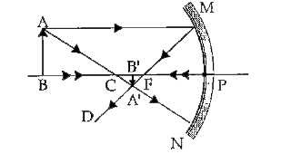
An image formed by concave mirror is virtual, when the object is placed:Aat infinityBat CCBetween C and FDBetween P and FFollowing figure illustrates the ray diagram for the formation of image by a concave mirror. The position of the object is beyond the centre of curvature of the concave mirror. On the basis of given diagram .
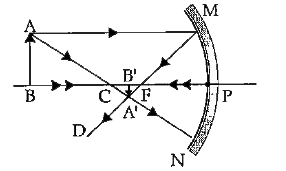
A negative sign in the magnification value indicate that the image is ____AReal and invertedBReal and erectCVirtual and erectDVirtual and inverted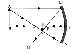
Above figure illustrates the ray diagram for the formation of image by a concave mirror. The position of the object is beyond the center of curvature of the concave mirror. On the basis of given diagram answer the following questions.
A negative sign in the magnification value indicates that the image is ________ .AReal and invertedBReal and erectCVirtual and erectDVirtual and inverted.
A student wants to project the image of a candle flame on the walls of the school laboratory by using a mirror.
Draw a ray diagram to show the formation of the image in this case.
View SolutionAn object is placed at a distance of 10 cm from a concave mirror of focal length 20 cm .
(i) Draw a ray diagram for the formation of image.
(ii) Calculate the image distance.
(iii) State two characteristics of the image formed.
View SolutionIt is desired to obtain an erect image of an object, using concave mirror of focal length of 12 cm.
(i) What should be the range of distance of an object placed in front of the mirror?
(ii) Will the image be smaller or larger than the object. Draw ray diagram to show the formation of image in this case.
(iii) Where will the image of this object be, if it is placed 24 cm in front of the mirror? Draw ray diagram for this situation also to justify your answer. Show the positions of pole, principal focus and the centre of curvature in the above ray diagrams.
View SolutionFollowing figure illustrates the ray diagram for the formation of image by a concave mirror. The position of the object is beyond the centre of curvature of the concave mirror. On the basis of given diagram .
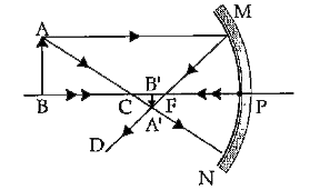
If the focal length of the concave mirror is 10 cm, the image formed will be at a distance ____
View SolutionFollowing figure illustrates the ray diagram for the formation of image by a concave mirror. The position of the object is beyond the centre of curvature of the concave mirror. On the basis of given diagram .
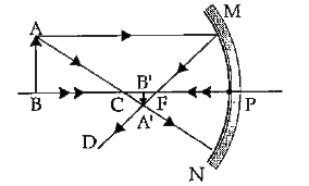
In case of concave mirror, the image distance is ____ when image is formed in front of the mirror and ____when the image is formed behind the mirror.
View Solution
