To verify Ohm's law, a student is provided with a test resistor RT, a high resistance R1, a small resistance R2, two identical galvanometer G1andG2, and a variable voltage source V. The correct circuit to carry out the experiment is
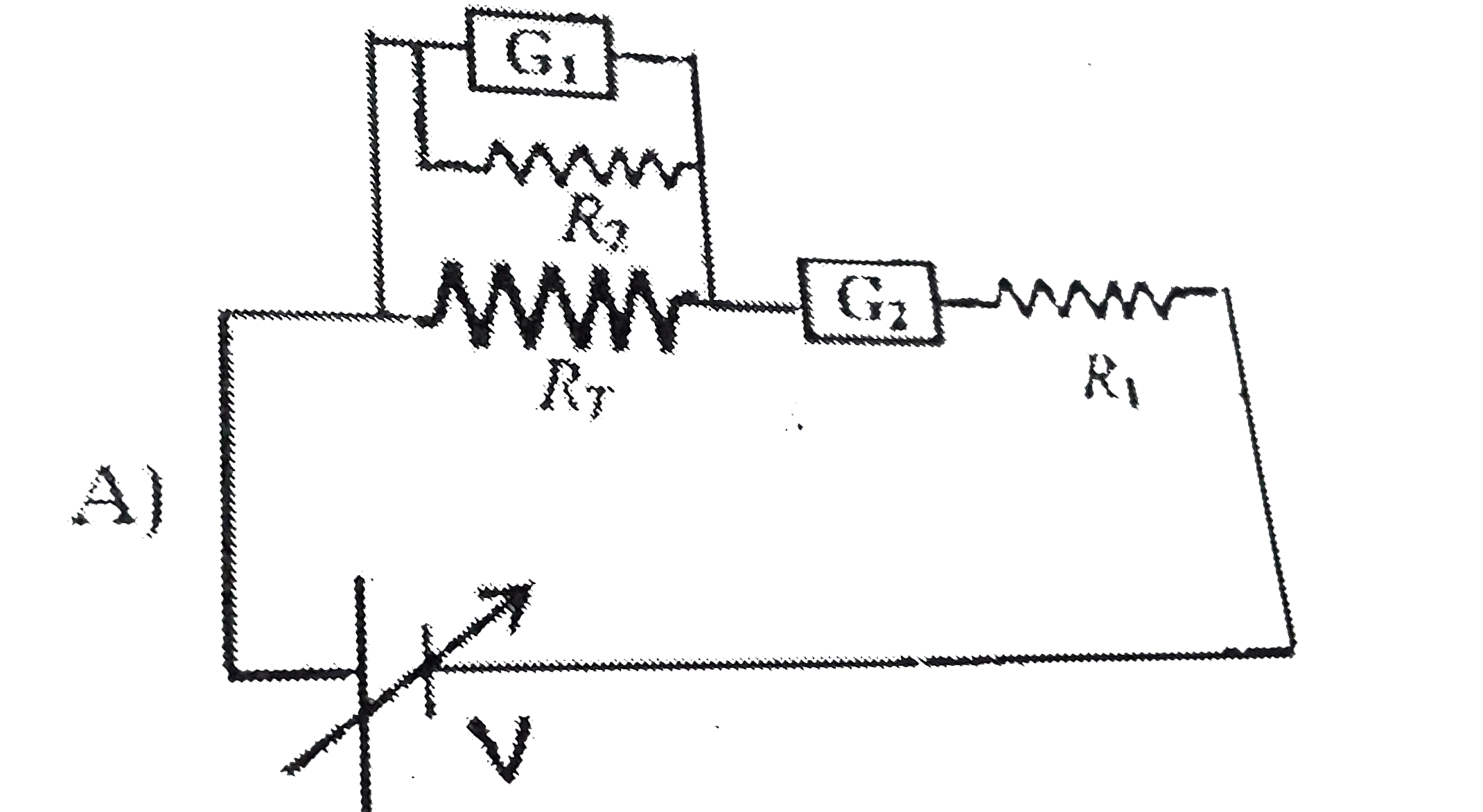
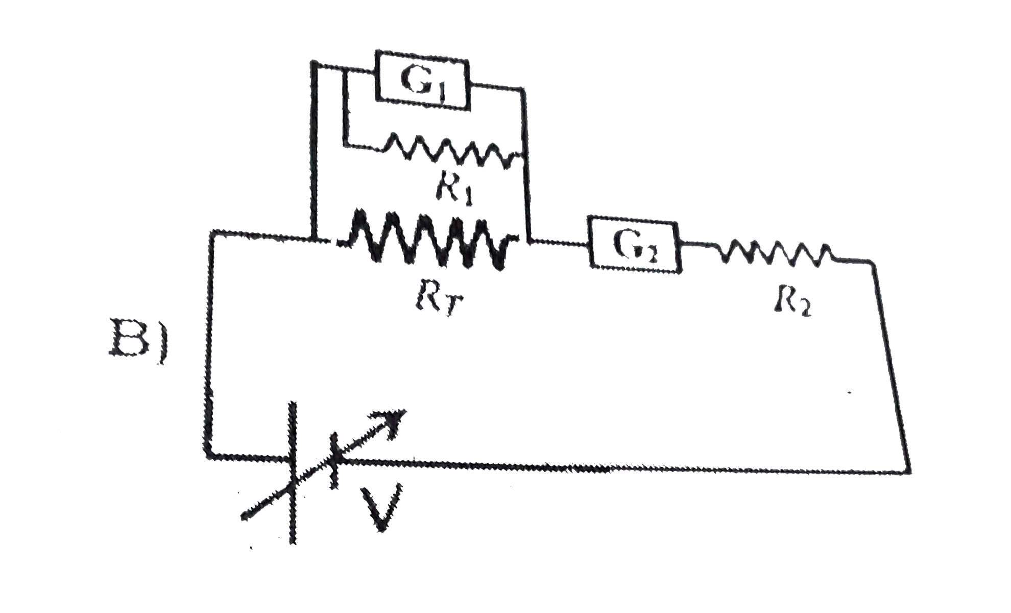
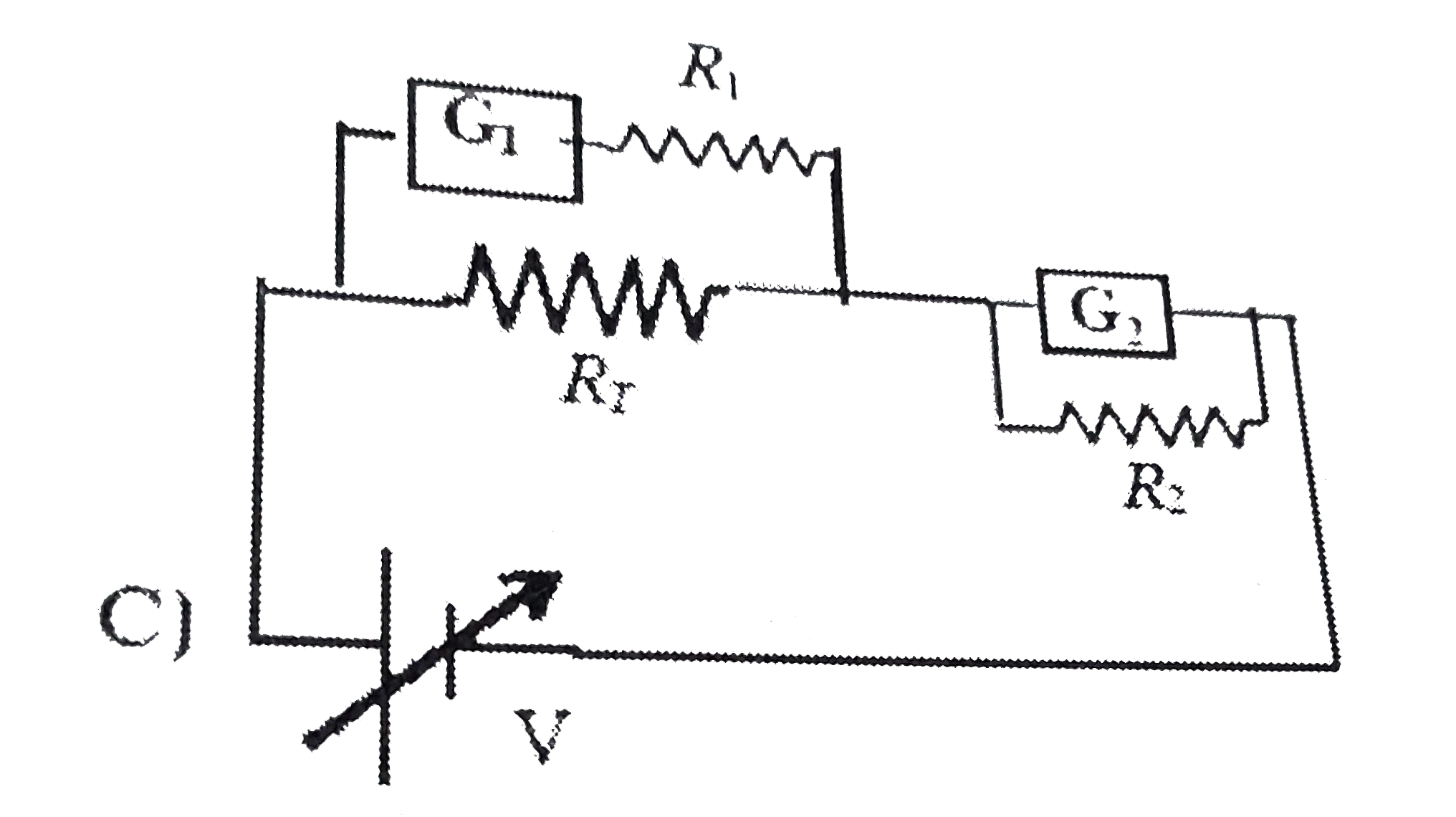

The correct Answer is:C
Step by step video, text & image solution for To verify Ohm's law, a student is provided with a test resistor R_T, a high resistance R_1, a small resistance R_2, two identical galvanometer G_1 and G_2, and a variable voltage source V. The correct circuit to carry out the experiment is by Physics experts to help you in doubts & scoring excellent marks in Class 12 exams.
Similar Questions
To verify Ohm's law, a student is provided with a test resistor RT, a high resistance R1 . a small resistance R2, two identical galvometers G1 and G2 and voltage source V. The correct circuit to carry out the experiment is.
View SolutionIn the curcuit given below D1 and D2 are two identicall diodes and V is a sinusoidal voltage source the voltage drop across the resistance RL
 View Solution
Knowledge Check
- Question 1 - Select One
If G, rA and rV denote the internal resistances of a galvanometer, an ammeter and a voltmeter among the following the correct relationship is
AG<rA<rVBrA<rV<GCrA<G<rVDrV<rA<G - Question 2 - Select One
If G,rA and rV denote the internal resistances of a galvanometer, an ammeter and a voltmeter among the following the correct relationship is
AG<rA<rVBrA<rV<GCrA<G<rVDrV<rA<G - Question 3 - Select One or More
Consider two identical galvanometers and two identical resistors with resistance R. If the internal resistance of the galvanometers Rc<R/2, which of the following statement(s) about any one of the galvanometers is (are) true?
AThe maximum voltage range is obtained when the two resistors and one galvanometer are connected in seriesBThe maximum voltage range is obtained when the two resistors and one galvanometer are connected in series , and the second galvanometer is connected in parallel to the first galvanometerCThe maximum current range is obtained when all the components are connected in parallelDThe maximum current range is obtained when the two galvanometers are connected in series and the combination is connected in parallel with both the resistors
Two resistors of resistance R1 and R2 having R1>R2 are connected in parallel. For equivalent resistance R, the correct statement is
View SolutionTwo resistors of resistance R1 and R2 having R1>R2 are connected in parallel. For equivalent resistance R, the correct statement is
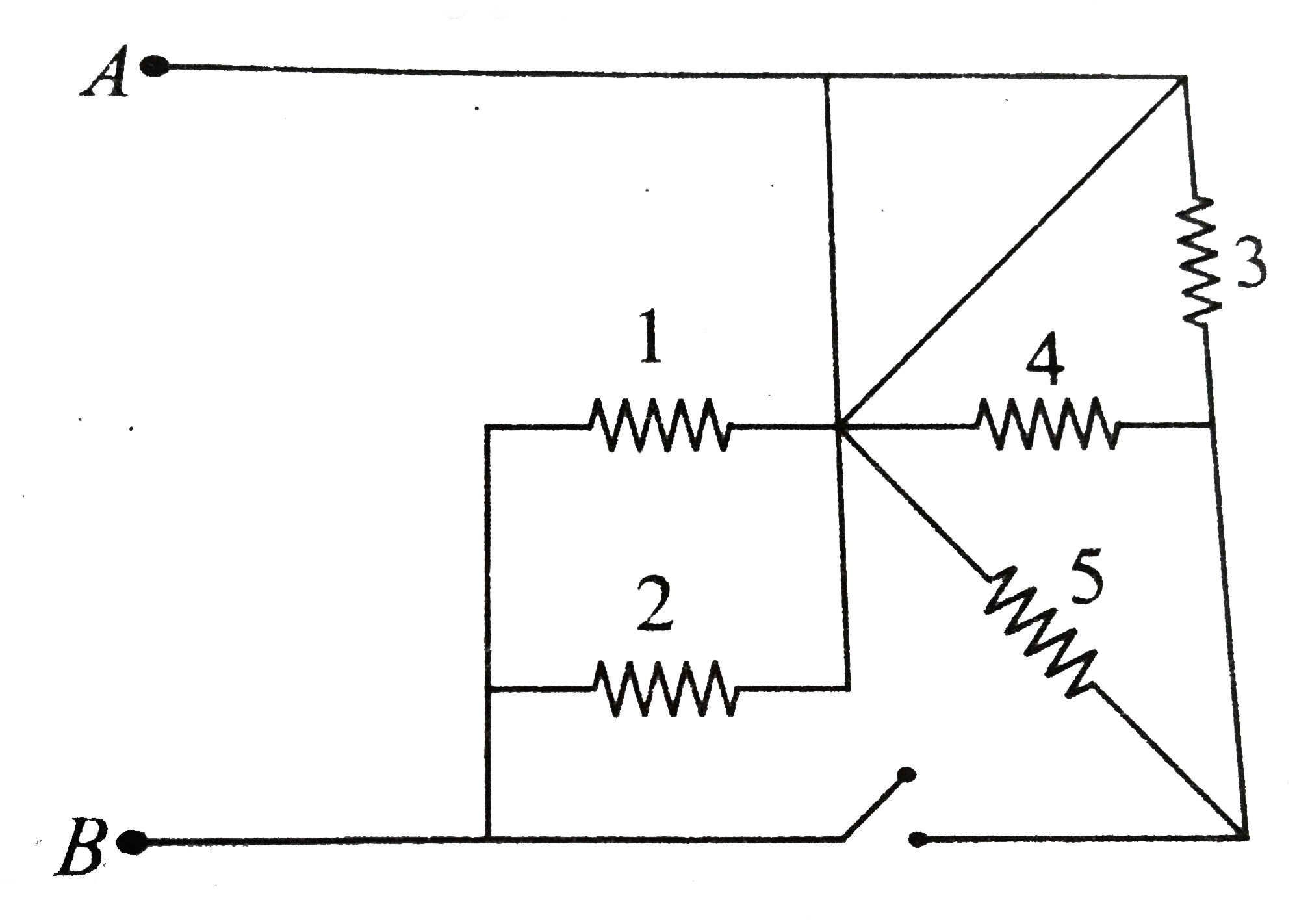
View SolutionThe circuit has resistors of equal resistance R. The equivalent resistance between A and B, when key is closed is R1 and when key is open is R2. Find the ratio R1andR2 .
 View Solution
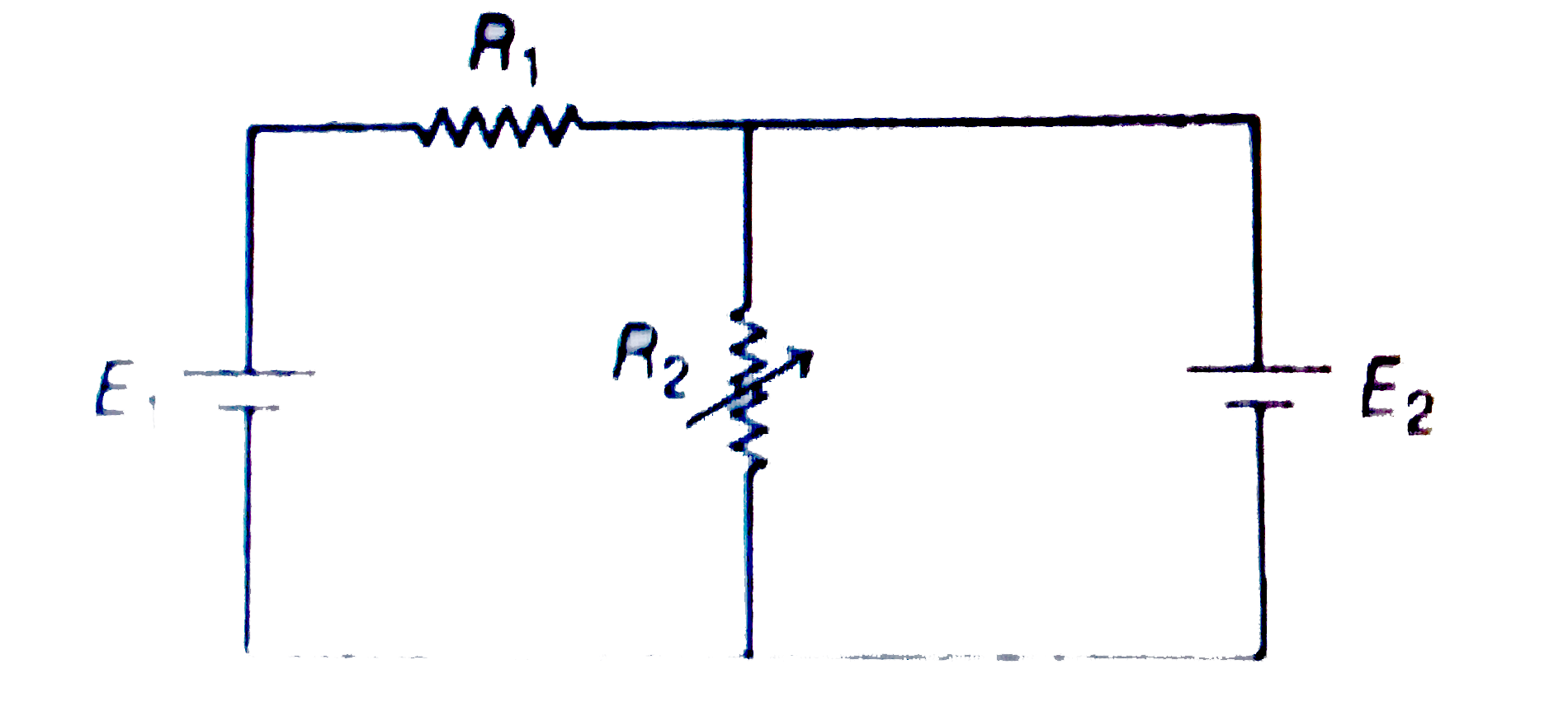
In the circuit shown, both cells are ideal and of fixed emf, the resistance of resistance R1 has fixed resistance and the resistance of resistor R2 can be varied (but the value of R2 is not zero). Then:
 View Solution
Two students made two circuits A and B to determine the resultant resistance of two resistors R1 and R2 connected in series :
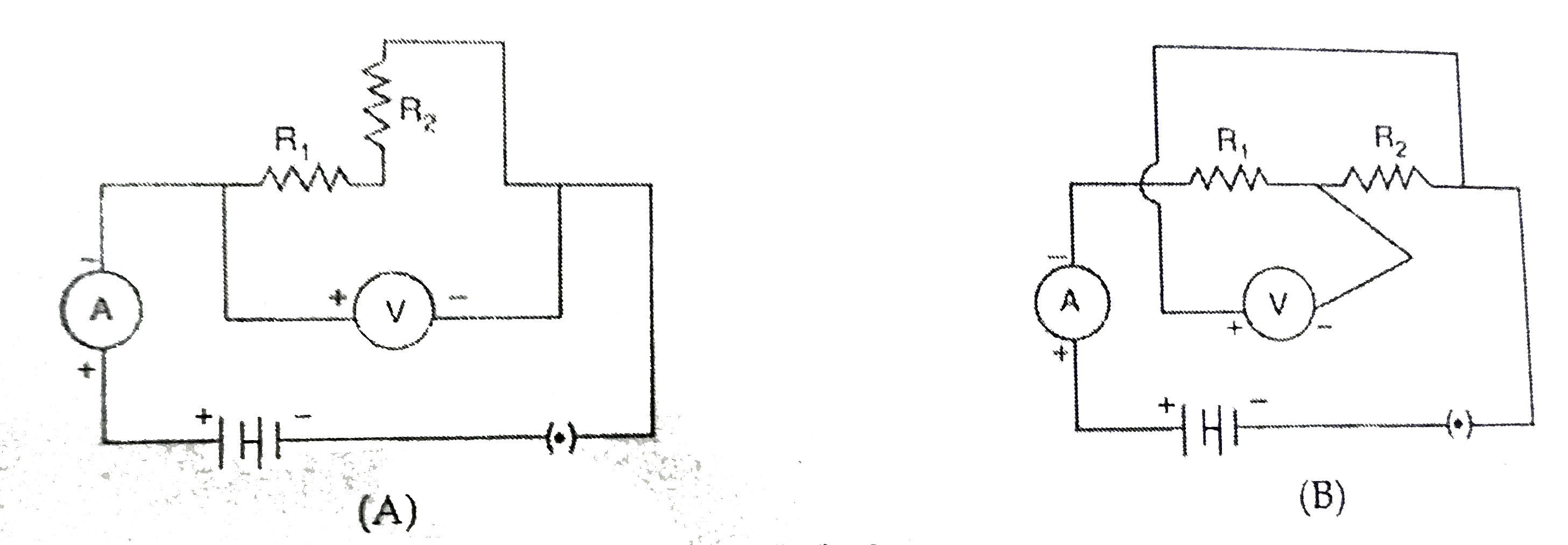
All the components have been connected correctly in :View Solution

