A rigid wire loop of square shape having side of length L and resistance R is moving along the x-axis with a constant velocity v0 in the plane of the paper. At t=0, the right edge of the loop enters a region of length 3L where there is a uniform magnetic field B0 into the plane of the paper, as shown in the figure. For sufficiently large v0 the loop eventually crosses the region. Let x be the location of the right edge of the loop. Let v(x), I(x) and F(x) represent the velocity of the loop, current in the loop, and force on the loop, respectively, as a function of x. Counter-clockwise current is taken as positive.
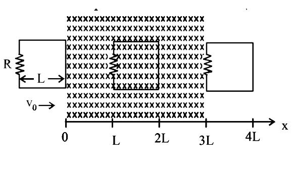 . Which of the following schematic plot(s) is (are) correct? (Ignore gravity)
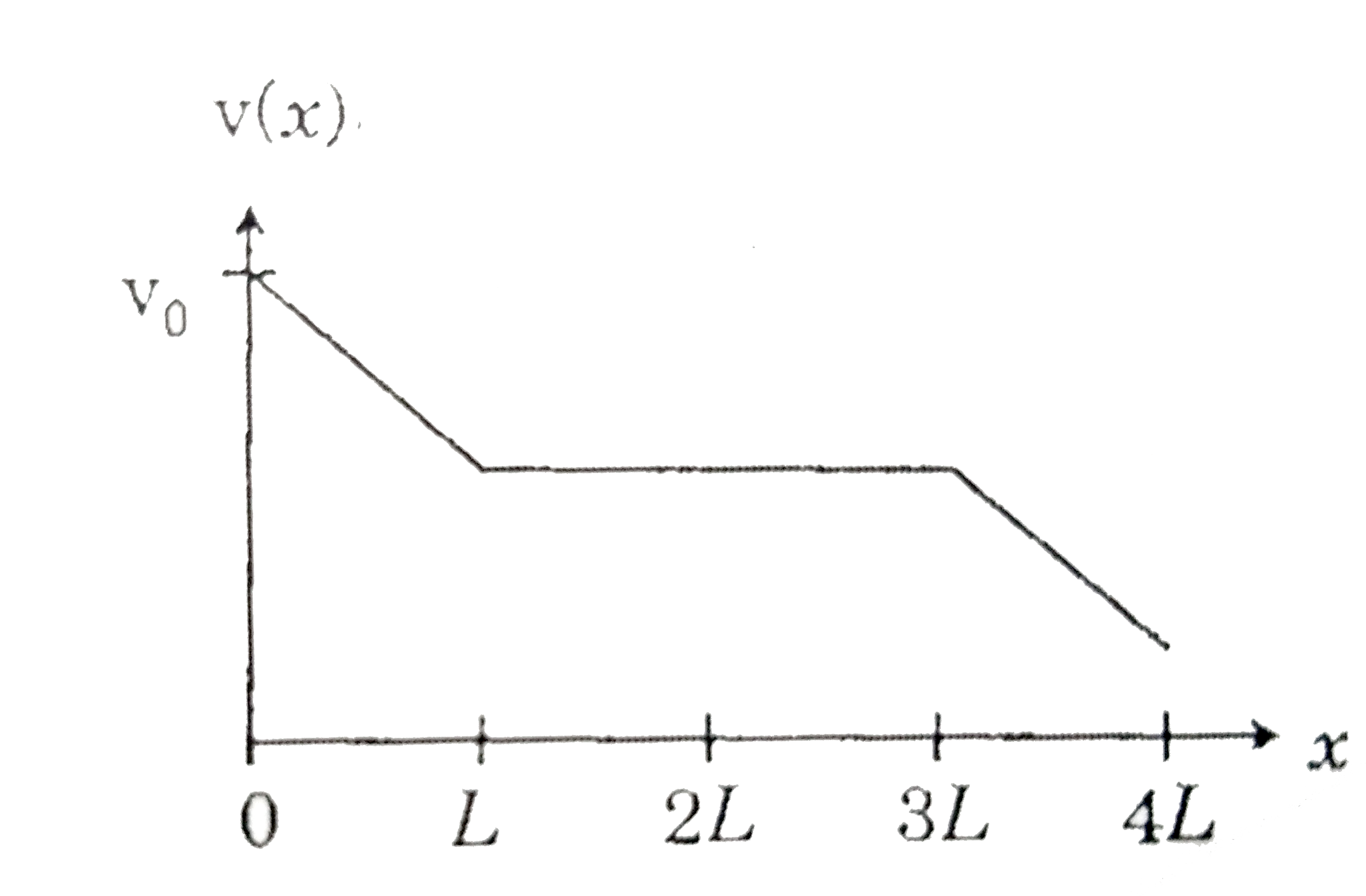
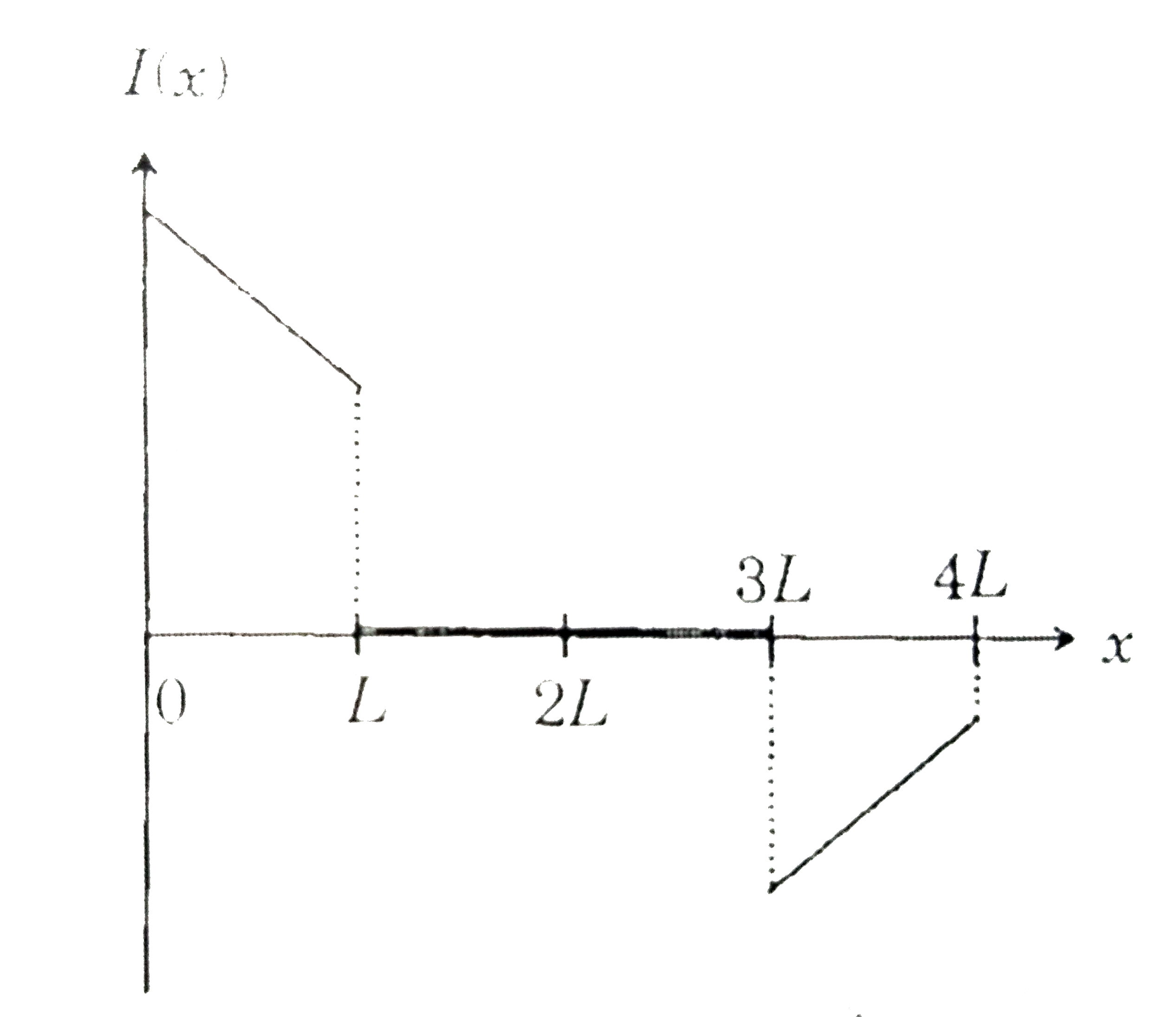
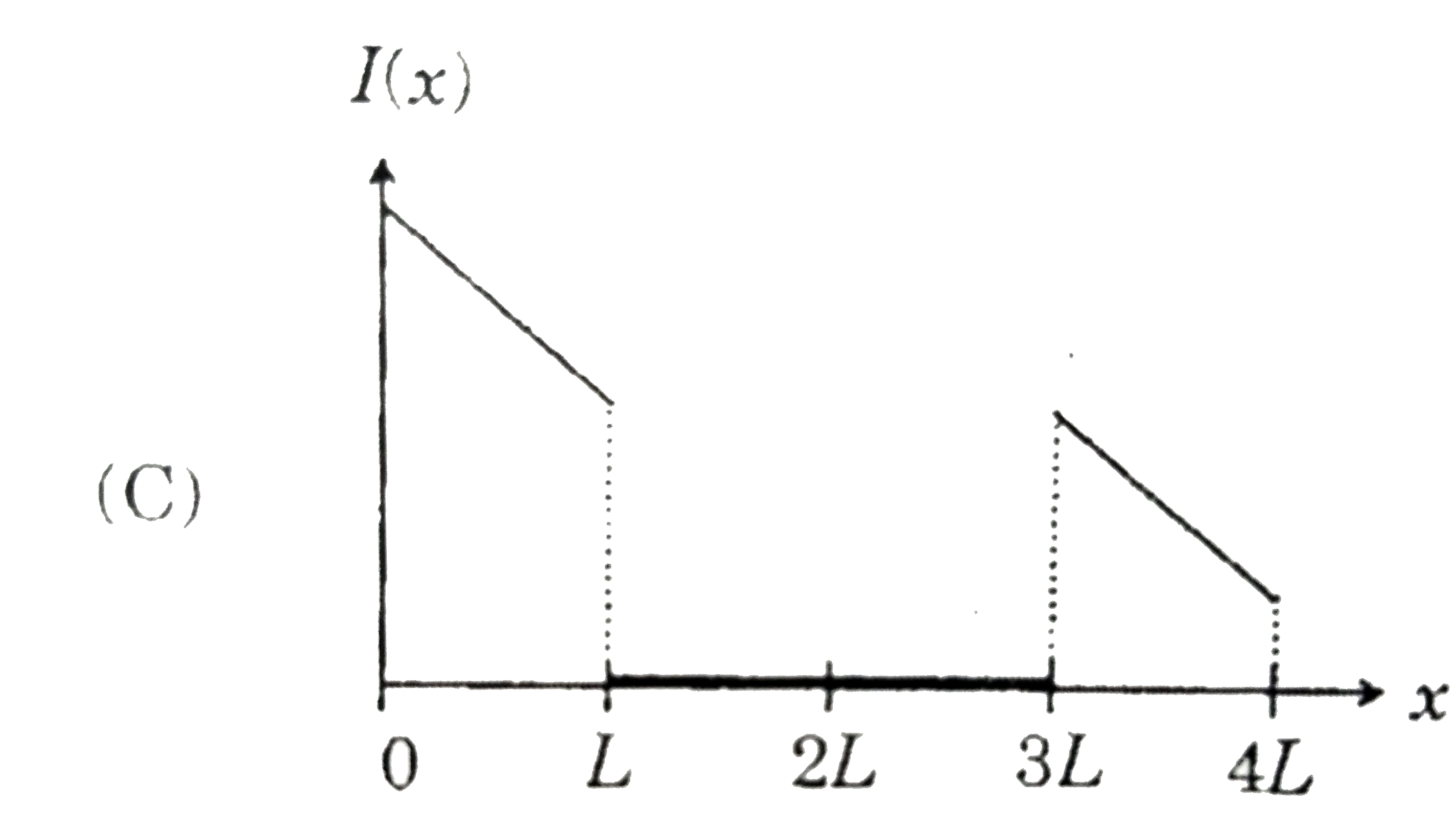
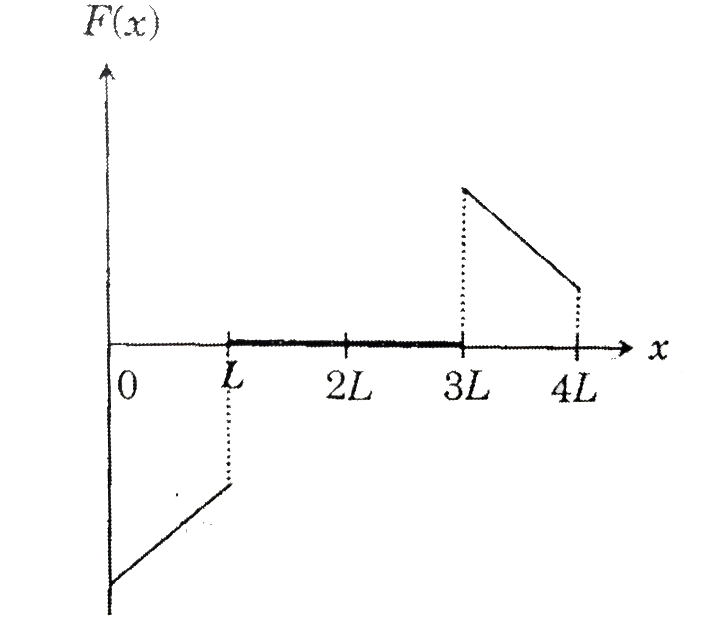
Step by step video & image solution for A rigid wire loop of square shape having side of length L and resistance R is moving along the x-axis with a constant velocity v_(0) in the plane of the paper. At t =0, the right edge of the loop enters a region of length 3L where there is a uniform magnetic field B_(0) into the plane of the paper, as shown in the figure. For sufficiently large v_(0) the loop eventually crosses the region. Let x be the location of the right edge of the loop. Let v(x), I(x) and F(x) represent the velocity of the loop, current in the loop, and force on the loop, respectively, as a function of x. Counter-clockwise current is taken as positive. . Which of the following schematic plot(s) is (are) correct? (Ignore gravity) by Physics experts to help you in doubts & scoring excellent marks in Class 12 exams.
Updated on:21/07/2023Similar Questions
एक वर्गीय आकृति वाला तार का दृढ़ फन्दा, जिसकी भुजा की लम्बाई L एवं प्रतिरोध R हैं, X-अक्ष की दिशा में एक स्थिर गति V0 से इस कागज के तल पर (Plane of the paper) गतिमान है। समय t=0 पर फन्दे का दाहिना किनारा 3L लम्बाई के स्थिर चुम्बकीय क्षेत्र B0, में प्रवेश करता है। चुम्बकीय रेखाओं की दिशा कागज के तल के लम्बवत् अन्दर की ओर हैं (जैसा चित्र में दर्शाया गया है)। ν0का मान पर्याप्त होने पर अन्ततोगत्वा फन्दा चुम्बकीय क्षेत्र को पार करता है। मान लीजिए कि फन्दे की दाहिनी भुजा स्थान पर है। फन्दे की गति, फन्दे में घारा एवं फन्दे पर बल की पर निर्भरता को क्रमशः v(x),I(x) एवं F(x) से निरूपित किया गया है। वामावर्त धारा को धनात्मक लें
निम्नलिखित में से कौन-सा/कौन-से व्यवस्था चित्र सही है//हैं? (गुरुत्वाकर्षण नगण्य माने)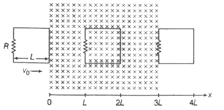
View SolutionA rectangular, a square, a circular and an elliptical loop, all in the x-y plane, are moving out of a uniform magnetic field with a constant velocity vcev = v_(0)hati . The magnetic field is directed along the negative z-axis direction. The induced emf, during the passage of these loops, out of the field region, will not remain constant for
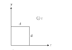
View Solutionकिसी क्षेत्र में चुम्बकीय क्षेत्र →B=B0(1+xa)ˆk द्वारा दिया जाता है। d भुजा का एक वर्गाकार लूप को क्षेत्र में इस प्रकार रखा जाता है ताकि इसकी दो आसन्न भुजाएँ क्रमशः x तथा y अक्ष के समानान्तर हो। लूप को नियत वेग →V=V0ˆi से गति कराया जाता है। लूप में प्रेरित वि.वा.बल है।
View SolutionThe magnetic field in a region is given by →B=B0(xa)ˆk. A square loop of side d is placed with its edges along the x and y axes. The loop is moved with a constant velocity →v=v0ˆi The emf induced in the loop is :
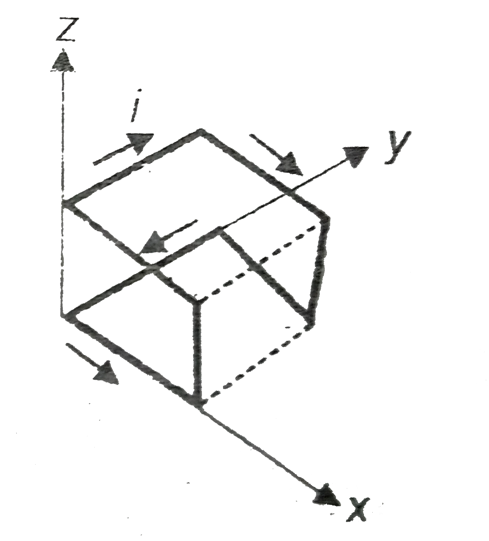
View SolutionThe figure shows a loop of wire carrying a current i as shown. There exists a uniform magnetic field along x-axis given by →B=B0ˆi. If the length of each side is a, then
View SolutionA rigid wire loop of square shape having side of length L and resistance R is moving along the x-axis with a constant velocity v_(0) in the plane of the paper. At t=0 , the right edge of the loop enters a region of length 3L where there is a uniform magnetic field B_(0) into the plane of the paper, as shown in the figure. For sufficiently large v_(0) , the loop eventually crosses the region. Let x be the location of the right edge of the loop. Let v(x),I_(x) and F_(x) represent the velocity of the loop, current in the loop, and force on the loop, respectively, as a function of x. Counter-clockwise curren is taken as positive. Which of the following schematic plots (s) is are correct ? (Ignore gravity )
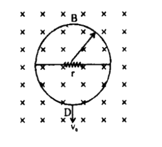
View SolutionA metallic ring (radius R) of negligible resistance has a resistance r connected across its diameter as shown in the figure. It is moving with velocity v0 in a constant magnetic field B0 acting perpendicular to the plane of the paper in the inward direction. The current in the resistance is :
View SolutionA square loop of side 10 cm and resistance 2Omega is moved with velocity v_(0) . The uniform magnetic field of 3T. With what speed the loop be moved as that a steady current of 1.5 mA flows in the loop.
View Solution
