Three identical capacitors C1,C2 and C3 have a capacitance of 1.0μF each and they are uncharged initially. They are connected in a circuit as shown in the figure and C1 is then filled completely with a dielectric material of relative permittivity εr. The cell electromotive force (emf) V0=8V. First the switch S1 is closed while the switch S2 is kept open. When the capacitor C3 is fully charged, S1 is opened and S2 is closed simultaneously. When all the capacitors reach equilibrium, the charge on C3 is found to be 5μc. The value of εr = ____________.
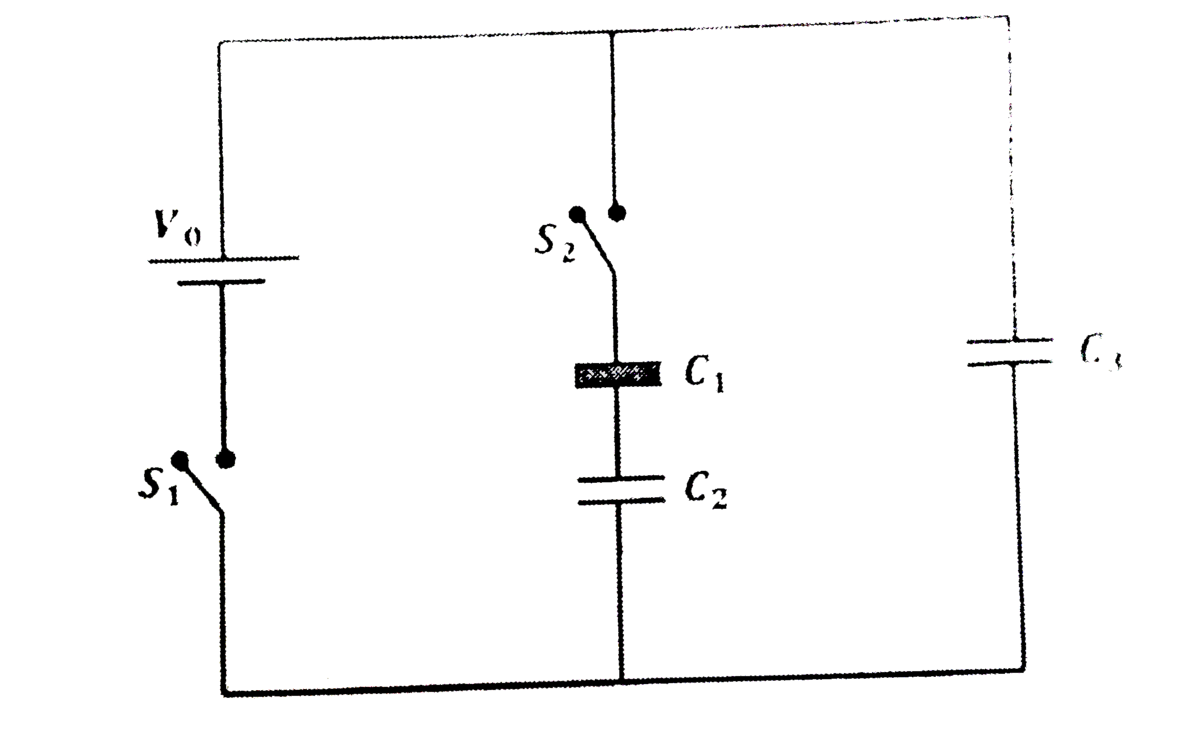
Step by step video & image solution for Three identical capacitors C_(1),C_(2) and C_(3) have a capacitance of 1.0 mu F each and they are uncharged initially. They are connected in a circuit as shown in the figure and C_(1) is then filled completely with a dielectric material of relative permittivity epsilon_(r). The cell electromotive force (emf) V_(0)=8V. First the switch S_(1) is closed while the switch S_(2) is kept open. When the capacitor C_(3) is fully charged, S_(1) is opened and S_(2) is closed simultaneously. When all the capacitors reach equilibrium, the charge on C_(3) is found to be 5 mu c. The value of epsilon_(r) = ____________. by Physics experts to help you in doubts & scoring excellent marks in Class 12 exams.
Updated on:21/07/2023Topper's Solved these Questions
- JEE ADVANCEDBOOK - JEE ADVANCED PREVIOUS YEARCHAPTER - JEE ADVANCEDEXERCISE - SECTION 3 PARAGRAPH 3
3 Videos
- JEE ADVANCEDBOOK - JEE ADVANCED PREVIOUS YEARCHAPTER - JEE ADVANCEDEXERCISE - PHYSICS SECTION - I : Single correct Answer Type
7 Videos
- JEE ADVANCEDBOOK - JEE ADVANCED PREVIOUS YEARCHAPTER - JEE ADVANCEDEXERCISE - SECTION 1
6 Videos
- JEE (ADVANCE) 2020BOOK - JEE ADVANCED PREVIOUS YEARCHAPTER - JEE (ADVANCE) 2020EXERCISE - SECTION 3
6 Videos
- JEE ADVANCED 2020BOOK - JEE ADVANCED PREVIOUS YEARCHAPTER - JEE ADVANCED 2020EXERCISE - SECTION-3
6 Videos
Similar Questions
Three identical capacitors C1,C2 and C3 of capacitance 6μF each are connected to a 12 V battery as shown in Fig
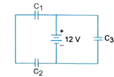
charge on each capacitor
View SolutionThree identical capacitors C1,C2 and C3 of capacitance 6μF each are connected to a 12 V battery as shown in Fig
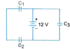
energy stored in the network of capacitors .
View Solution
Knowledge Check
In the circuit shown initially C1,C2 are uncharged. After closing the switch
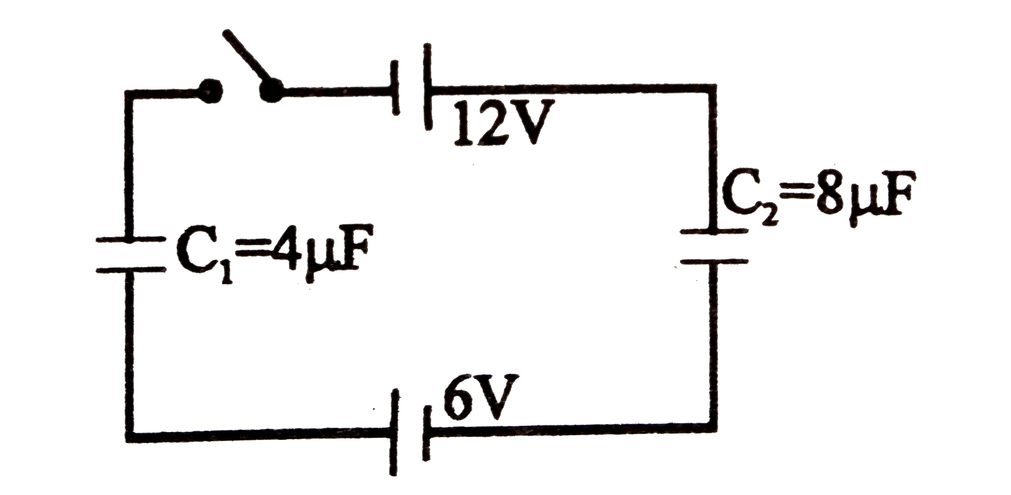 AThe charge on C2 is greater that on C1BThe charge on C1 and C2 are the sameCThe potential drops across C1 and C2 are the sameDThe potential drops across C2 is greater than that across C1
Two capacitors C1 and C2 are connected in a circuit as shown in figure. The potential difference (VA−VB) is
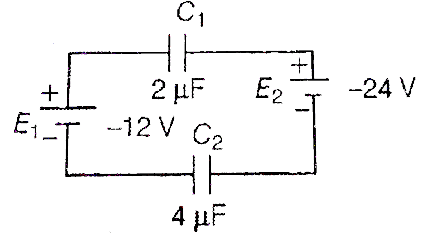 A8VB−8VC12VD12V
In the circuit shown, the capacitor initially charged with a 12V batteryy, when switch S1 is open and switch S2 is closed. The maximum value of current in the circuit when S2 is opened and S2 is closed is
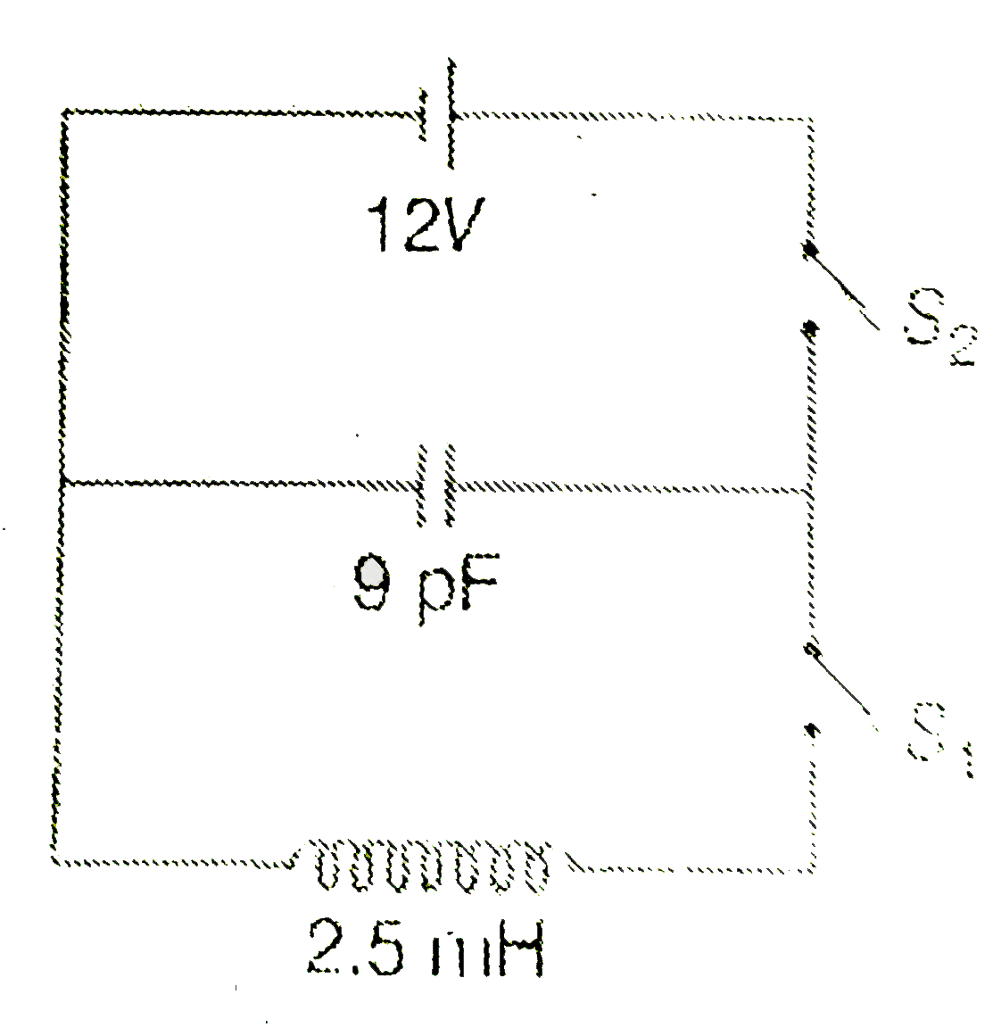 A10−6AB7.2μAC720μAD360μA
Three identical capacitors C1,C2 and C3 of capacitance 6μF each are connected to a 12 V battery as shown in Fig
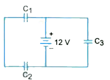
equivalent capacitance of the network
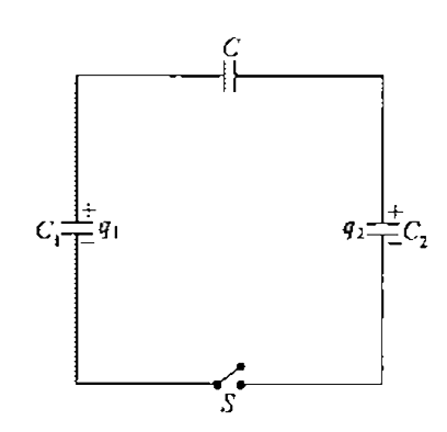
View SolutionTwo capacitor C1 and C2, charged with chargesq1 and q2 then these are connected in series with an uncharged capacitor C, as shown in figure. As the switch S is closed :
View SolutionIn the circuit shown in the figure, if switches S1 and S2 have been closed for a long time, then charge on the capacitor.
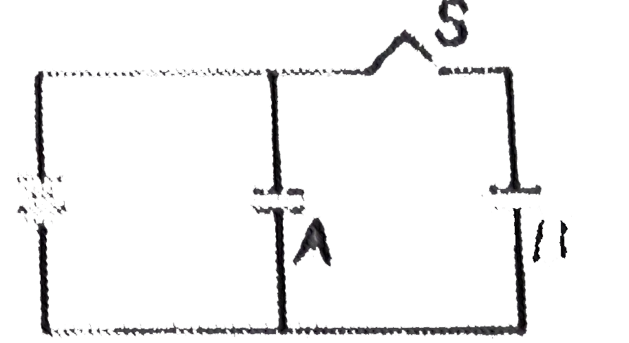
View SolutionTwo identical air filled parallel plate capacitors are charged to the same potential in the manner shown by closing the switch S. If now the switch S is opened and the space between the plates is filled with a dielectric of relative permittivity εt, then
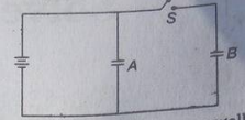
View SolutionTwo identical air filled parallel plate capacitors are changed to the same potential in the manner shown by closing the switch S. If now the switch S is opened and the space between the plates is filled with a dielectric of relative permittivity εr, then
View Solution
