Can the potential barrier across a p-n junction be measured by simply connecting a voltmeter across the junction ?
No, we cannot measure the potential barrier across a p-n junction by simply connecting a voltmeter across the junction because resistance across the junction is almost infinite and no current will flow through the voltmeter.
Topper's Solved these Questions
- SEMICONDUCTOR ELECTRONICS : MATERIALS, DEVICES AND SIMPLE CIRCUITSBOOK - U-LIKE SERIESCHAPTER - SEMICONDUCTOR ELECTRONICS : MATERIALS, DEVICES AND SIMPLE CIRCUITSEXERCISE - SHORT ANSWER QUESTIONS
28 Videos
- SEMICONDUCTOR ELECTRONICS : MATERIALS, DEVICES AND SIMPLE CIRCUITSBOOK - U-LIKE SERIESCHAPTER - SEMICONDUCTOR ELECTRONICS : MATERIALS, DEVICES AND SIMPLE CIRCUITSEXERCISE - LONG ANSWER QUESTIONS-I
22 Videos
- SEMICONDUCTOR ELECTRONICS : MATERIALS, DEVICES AND SIMPLE CIRCUITSBOOK - U-LIKE SERIESCHAPTER - SEMICONDUCTOR ELECTRONICS : MATERIALS, DEVICES AND SIMPLE CIRCUITSEXERCISE - ASSERTION-REASON TYPE QUESTIONS
5 Videos
- RAY OPTICS AND OPTICAL INSTRUMENTSBOOK - U-LIKE SERIESCHAPTER - RAY OPTICS AND OPTICAL INSTRUMENTSEXERCISE - SELF ASSESSMENT TEST (SECTION B)
3 Videos
- WAVE OPTICSBOOK - U-LIKE SERIESCHAPTER - WAVE OPTICSEXERCISE - SELF ASSESSMENT TEST SECTION C (VERY SHORT ANSWER QUESTIONS)
4 Videos
Similar Questions
Knowledge Check
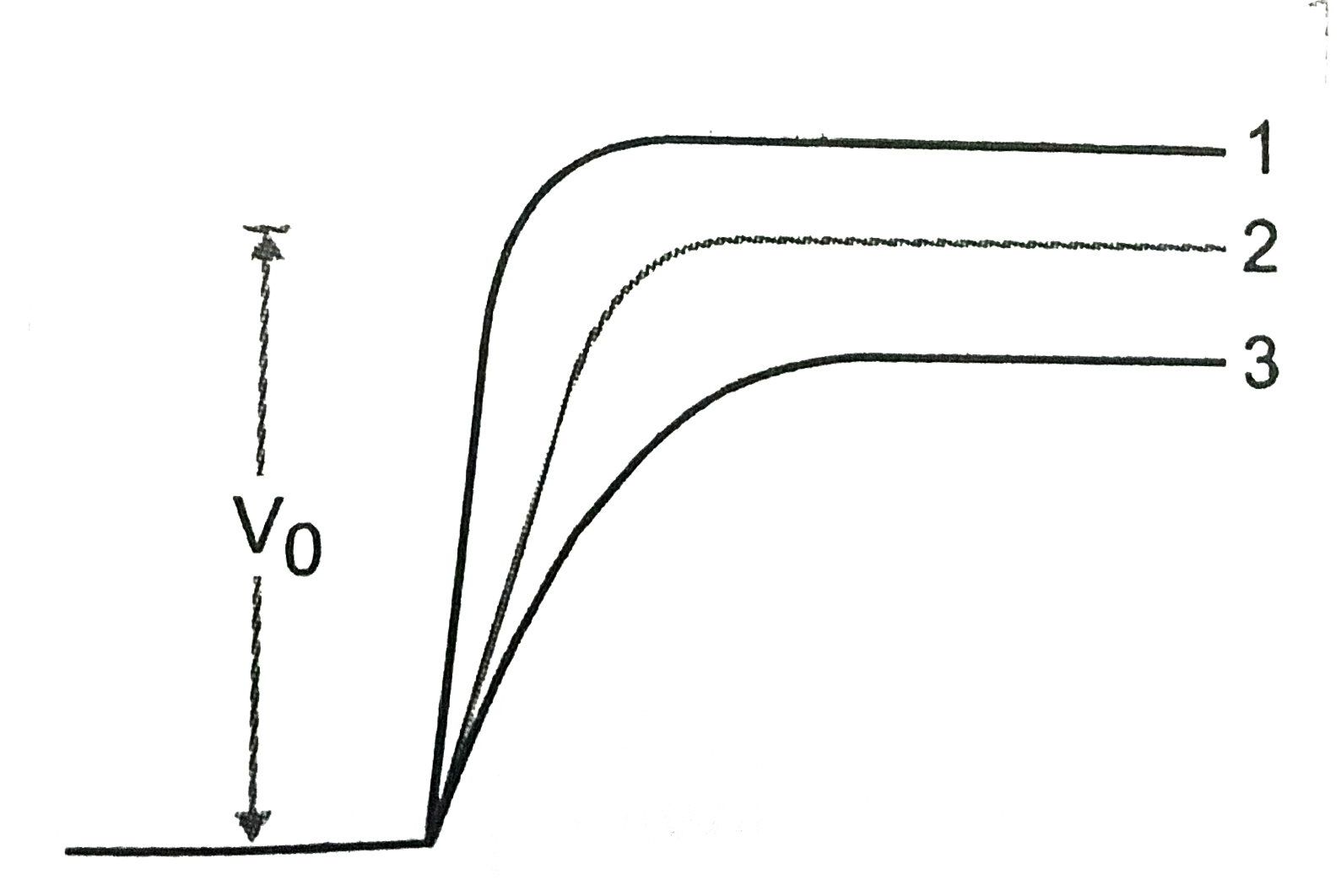
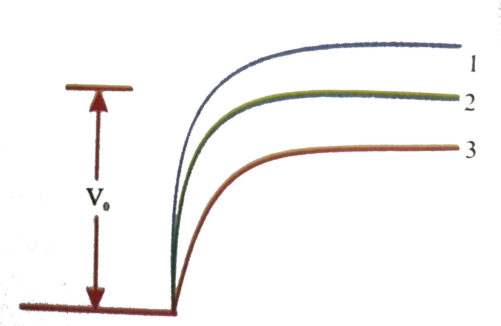
In Fig . V0 is the potential barrier across a p-n junction, when no battery is connected across the junction
 A1 and 3 both correspond to forward bias of junctionB3 corresponds to forward bias of junction and 1 corresponds to reverse bias of junctionC1 corresponds to forward bias and 3 corresponds to reverse bias of junctionD3 and 1 both correspond to reverse bias of junction
In Fig. V0 is the potential barrier across a p−n junction, when no battery is connected across the junction :
 .A1 and 3 both correspond is forward bias of junctionB3 corresponds to forward bias of junction and 1 corresponds to reverse bias junctionC1 corresponds to forward bias and 3 corresponds to reverse bias junctionD3 and 1 both correspond to reverse bias and 3 corresponds to revers bias of junction
In Fig . V0 is the potential barrier across a p-n junction, when no battery is connected across the junction
 A1 and 3 both correspond to forward bias of junctionB3 corresponds to forward bias of junction and 1 corresponds to reverse bias of junctionC1 corresponds to forward bias and 3 corresponds to reverse bias of junction.D3 and 1 both correspond to reverse bias of junction.
How is a potential barrier formed in p-n junction diode ?
View Solutionp-n junction is a semiconductor diode. It is obtained by bringing p-type semiconductor inclose contact with n-type semiconductor. A thin layer is developed at the p-n junction which is devoid of any charge carrier but has immobile ions. It is called depletion layer. At the junction a potential barrier appears, which does not allow the movement of majority charge carriers across the junction in the absence of any biasing of the junction.
p-n junction offer low resistance when forward biased and high resistance when reverse biased. Read the above paragaph and answer the following question:
(i) Can we measure the potential barrier of p-n junction by putting a sensitive voltmeter across its terminals?
(ii) What practical lesson do you draw from the above study?
View SolutionCan we measure the potential difference of a p-n junction by putting a sensitive voltmeter across its terminals?
View SolutionAssertion: We can measure the potential barrier of a PN junction by putting a sensitive voltmeter across its terminals.
Reason: The current through the PN junction is not same in forward and reversed bias.
View SolutionAssertion : We cannot meausre that potential barrier of p-n junction by putting a sensitive voltmeter across its terminals.
Reason: In the depletion layer, there are no free elctrons or holes and in the absence of forward bias, it offers, infinite, resistance.
View Solution
