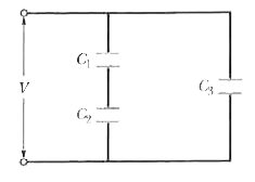
Find the equivalent capacitance for the combination of capacitances shown in fig.25-10a, across which potential difference V is applied . Assume
(a) C1=12.0μF,C2=5.30μFandC3=4.50μF
(b) The potential difference applied to the input terminals in fig.25-10a is V=12.5V What is the charge on C1?
To solve the problem step by step, we will first find the equivalent capacitance of the circuit and then calculate the charge on capacitor C1.
Step 1: Identify the Configuration of Capacitors
In the given circuit, capacitors C1 and C2 are in parallel, and their combination is in series with capacitor C3.
Step 2: Calculate the Equivalent Capacitance of C1 and C2
For capacitors in parallel, the equivalent capacitance C12 is given by:
C12=C1+C2
Substituting the values:
C12=12.0μF+5.30μF=17.30μF
Step 3: Calculate the Total Equivalent Capacitance
Now, C12 is in series with C3. The equivalent capacitance Ceq for capacitors in series is given by:
1Ceq=1C12+1C3
Substituting the values:
1Ceq=117.30μF+14.50μF
Calculating the right-hand side:
1Ceq=117.30+14.50=4.50+17.3017.30×4.50
=21.8077.85⟹Ceq=77.8521.80≈3.57μF
Step 4: Calculate the Charge on the Equivalent Capacitance
The charge Qeq on the equivalent capacitance when a potential difference V is applied is given by:
Qeq=Ceq×V
Substituting the values:
Qeq=3.57μF×12.5V=44.625μC
Step 5: Calculate the Voltage Across Capacitors C1 and C2
Since C1 and C2 are in parallel, they share the same voltage V12:
V12=QeqC12=44.625μC17.30μF≈2.58V
Step 6: Calculate the Charge on Capacitor C1
The charge Q1 on capacitor C1 can be calculated using:
Q1=C1×V12
Substituting the values:
Q1=12.0μF×2.58V=31.0μC
Final Answer
The charge on capacitor C1 is 31.0μC.
---
In the given circuit, capacitors C1 and C2 are in parallel, and their combination is in series with capacitor C3.
For capacitors in parallel, the equivalent capacitance C12 is given by:
C12=C1+C2
Substituting the values:
C12=12.0μF+5.30μF=17.30μF
Now, C12 is in series with C3. The equivalent capacitance Ceq for capacitors in series is given by:
1Ceq=1C12+1C3
Substituting the values:
1Ceq=117.30μF+14.50μF
Calculating the right-hand side:
1Ceq=117.30+14.50=4.50+17.3017.30×4.50
=21.8077.85⟹Ceq=77.8521.80≈3.57μF
The charge Qeq on the equivalent capacitance when a potential difference V is applied is given by:
Qeq=Ceq×V
Substituting the values:
Qeq=3.57μF×12.5V=44.625μC
Since C1 and C2 are in parallel, they share the same voltage V12:
V12=QeqC12=44.625μC17.30μF≈2.58V
The charge Q1 on capacitor C1 can be calculated using:
Q1=C1×V12
Substituting the values:
Q1=12.0μF×2.58V=31.0μC
The charge on capacitor C1 is 31.0μC.
Topper's Solved these Questions
- CAPACITANCEBOOK - RESNICK AND HALLIDAYCHAPTER - CAPACITANCEEXERCISE - CHECKPOINTS
4 Videos
- CAPACITANCEBOOK - RESNICK AND HALLIDAYCHAPTER - CAPACITANCEEXERCISE - PROBLEMS
48 Videos
- ALL ABOUT ATOMS BOOK - RESNICK AND HALLIDAYCHAPTER - ALL ABOUT ATOMS EXERCISE - CHECKPOINT
1 Videos
- CENTER OF MASS BOOK - RESNICK AND HALLIDAYCHAPTER - CENTER OF MASS EXERCISE - Practice Questions (Integer )
4 Videos
Similar Questions
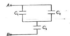
(a ) Find the equivalent capacitance of the combination shown in the figure ( a) when C1=2.0μF,C2=4.0μF and C3=3.0μF
(b ) The input terminals A and B in figure (a) are connected to a battery of 12 V. Find the potential and the charge of each capacitor .
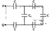
View SolutionFind the equivalent capacitance between P and Q if C1=6μFandC=9μF
View Solution
Knowledge Check
In the arrangement C1=10μ,FC2=10μF and C3=20μF . What is the equivalent capacitance ( in μF ) between points A and B ?
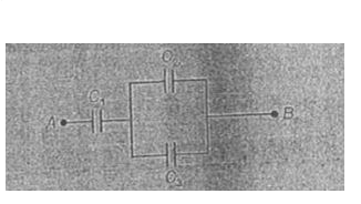 A7.5B10C12D15
Find the charges on the three capacitors connected to a battery as shown in figure. Take C1=2.0μF,C2,=4.0μF,C3=6.0μF and V =10 volt
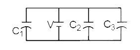 A20μC,40μC,60μCB40μC,20μC,60μCC60μC,40μC,20μCD40μC,60μC,20μC
The equivalent capacitance of the combination between A and B in the given figure is 4μF .
What will be the potential drop across each capacitor ?

View SolutionThe equivalent capacitance of the combination between A and B in the given figure is 4μF .
Calculate capacitance of the capacitor C.

View SolutionCalculate the potential difference and the energy stored in the capacitor C2 in the circuit shown in the Fig. Given potential at A is 90 V , C1=20μF,C2=30μF and C3=15μF

View SolutionIn Fig, 25-26 , find the equivalent capacitance of the combination. C1 is 10.0μF,C2 is 8.00μF, and C3 is 4.00μF
View Solution(a) Find the equivalent capacitance of the combination between A and B in the figure
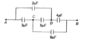
If the points A and B are maintained at 15 V and 0 V respectively then
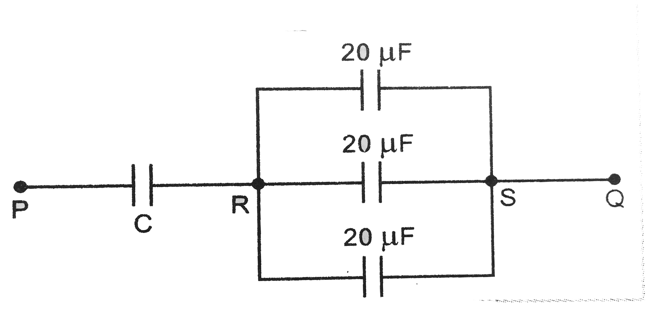
View SolutionCalculate the capacitance of the capacitance of the capacitor C in Fig. The equivalent capacitance of the combination between P and Q is 30μF
View Solution
