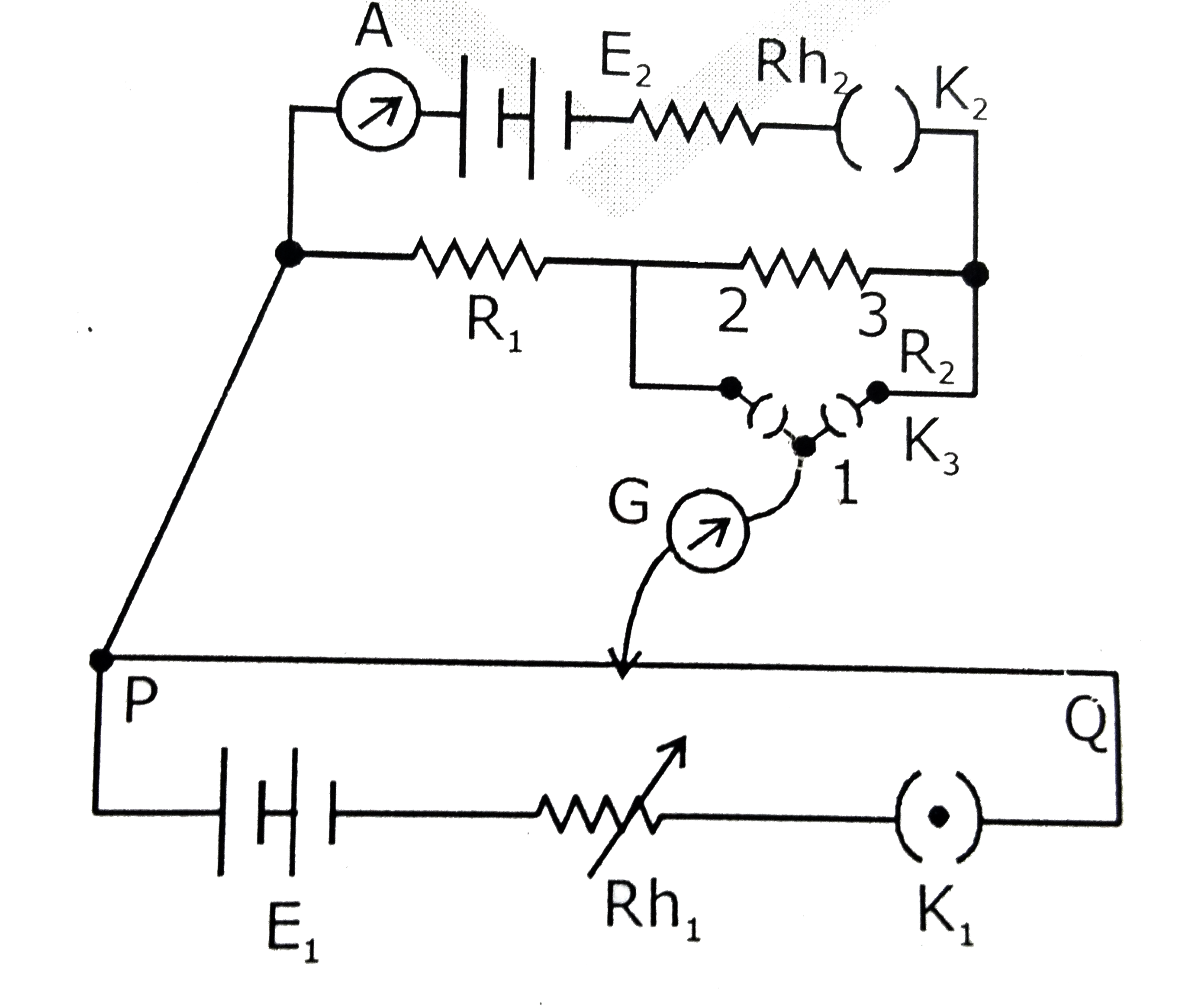
A potentiometer PQ is set up to compare two resistance as shown in the figure. The ammeter A in the circuit reads 1.0 A when two way key K3 is open. The balance point is at amlength l1 cm from P when two way key K3 is plugged in between 2 and 1, while the balance point is at length l2 cm from P when key K3 is plugged in between 3 and 1. The ratio of two resistance R1R2, is found to be:

l1l1+l2
l2l2−l1
l1l1−l2
l1l2−l1
The correct Answer is:D
When key is plugged between points (1) and (2) then only resistance R1 is in the circuit.
V1=iR1∝l1…(i)
When key is plugged between (3) and (1) V2=i(R1+R2)∝l2 (ii)
Dividing the above two equations we get the following:
R1R1+R2=l1l2⇒R1R2=l1l2−l1
Topper's Solved these Questions
- CURRENT ELECTRICITYBOOK - MODERN PUBLICATIONCHAPTER - CURRENT ELECTRICITYEXERCISE - Objective Type Questions (MULTIPLE CHOICE QUESTIONS) (B. MULTIPLE CHOICE QUESTION JEE (ADVANCED) FOR IIT ENTRANCE)
9 Videos
- CURRENT ELECTRICITYBOOK - MODERN PUBLICATIONCHAPTER - CURRENT ELECTRICITYEXERCISE - Objective Type Questions (MULTIPLE CHOICE QUESTIONS) (C. MULTIPLE CHOICE QUESTIONS WITH MORE THAN ONE CORRECT ANSWER)
18 Videos
- CURRENT ELECTRICITYBOOK - MODERN PUBLICATIONCHAPTER - CURRENT ELECTRICITYEXERCISE - Objective Type Questions (MULTIPLE CHOICE QUESTIONS) (B. MULTIPLE CHOICE QUESTION FOR COMPETITIVE EXAMINATIONS)
20 Videos
- ATOMS BOOK - MODERN PUBLICATIONCHAPTER - ATOMS EXERCISE - Chapter Practice Test
16 Videos
- DUAL NATURE OF RADIATION AND MATTER BOOK - MODERN PUBLICATIONCHAPTER - DUAL NATURE OF RADIATION AND MATTER EXERCISE - CHAPTER PRACTICE TEST
15 Videos
Similar Questions
A potentiometer PQ is set up to comapre two resistances as shown in the figure. The ammeter A in the circuit reads 1.0 A when two way key K3 is open. The balance point is at a length l1 cm from P when two way key K3 is plugged in between 2 and 1, while the balance point is at a length l2 cm from P when key K3 is plugged in between 3 and 1. The ratio of the two resistance R1R2, is found to be-

View SolutionA potentiometer PQ is set up to comapre two resistances as shown in the figure. The ammeter A in the circuit reads 1.0 A when two way key K3 is open. The balance point is at a length l1 cm from P when two way key K3 is plugged in between 2 and 1, while the balance point is at a length l2 cm from P when key K3 is plugged in between 3 and 1. The ratio of the two resistance R1R2, is found to be-

View Solution
Knowledge Check
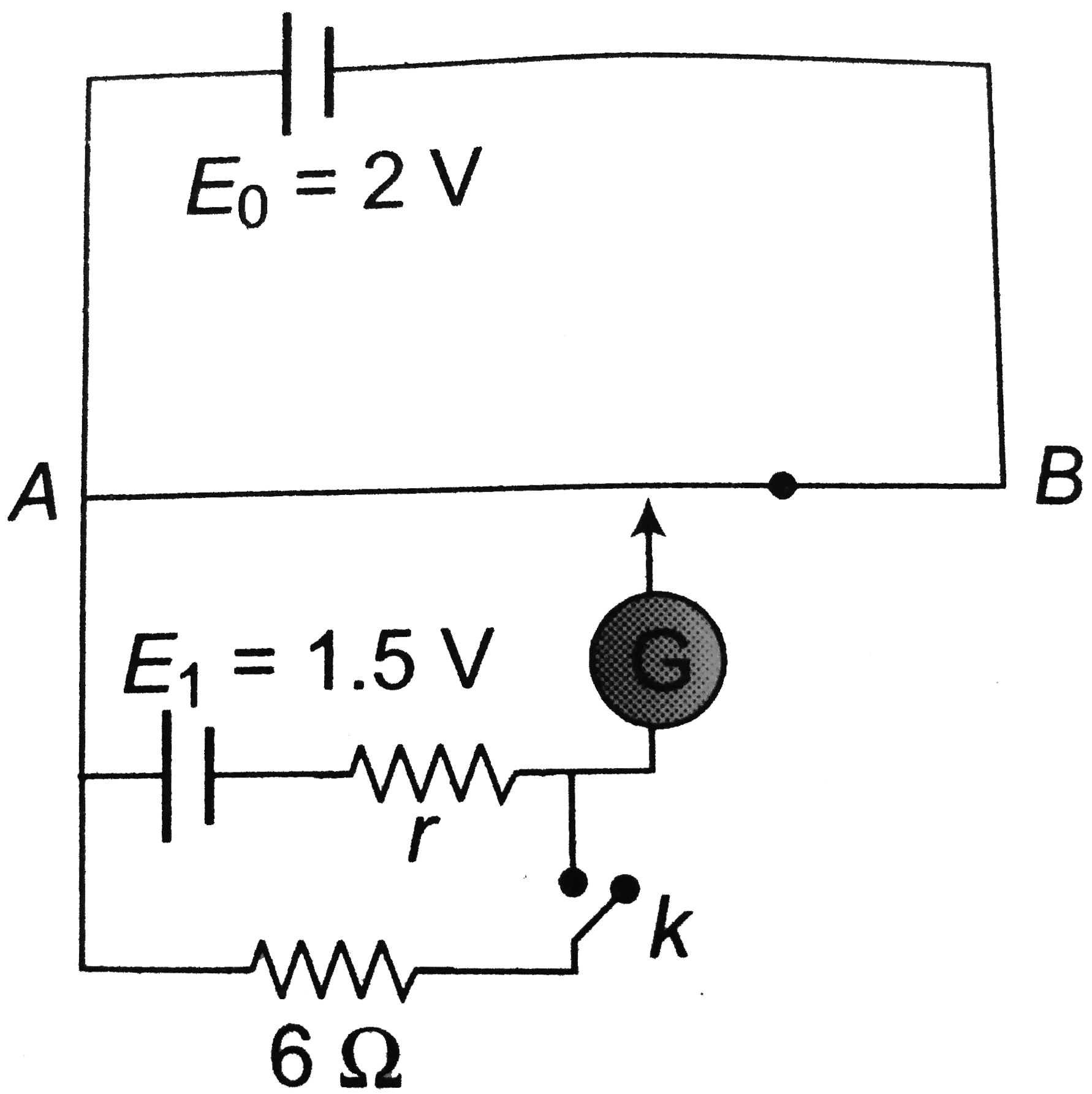
For the arrangement of the potentiometer shown in the figure, The balance point is obtained at a distance 75cm from A when the key k is open
The second balance point is obtained at 60cm from A when the key k is closed. Find the internal resistance of the battery E1.
 A1.5ΩB2ΩC0.5ΩD1Ω
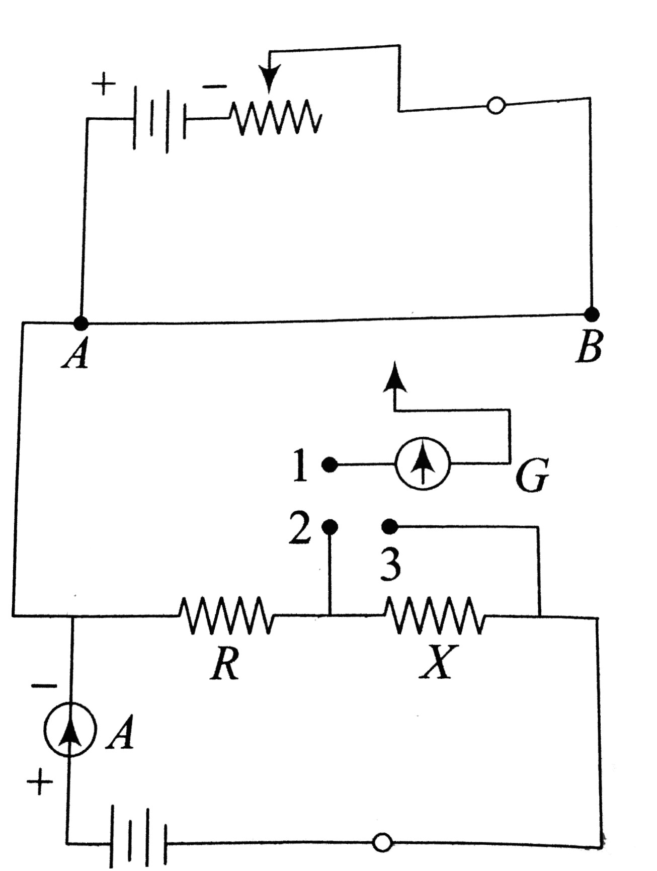
A potentiometer circuit is setup as shown. The potential gradient across the potentiometer wire is kvolt/cm and the ammeter present in the circuit reads. 1.0A When two-way key is switched off. The balance point, when the key between the terminals (i) 1 and 2 (ii) 1 and 3, is plugged in, are found to be at lengths l2cm and l2cm respectively. The magnitudes, of the resistors R and X, in ohm, are then, equal, respectively, to
 Ak(l2−l1) and kl2Bkl1 and k(l2−l1)Ck(l2−l1) and kl1Dkl1 and kl2
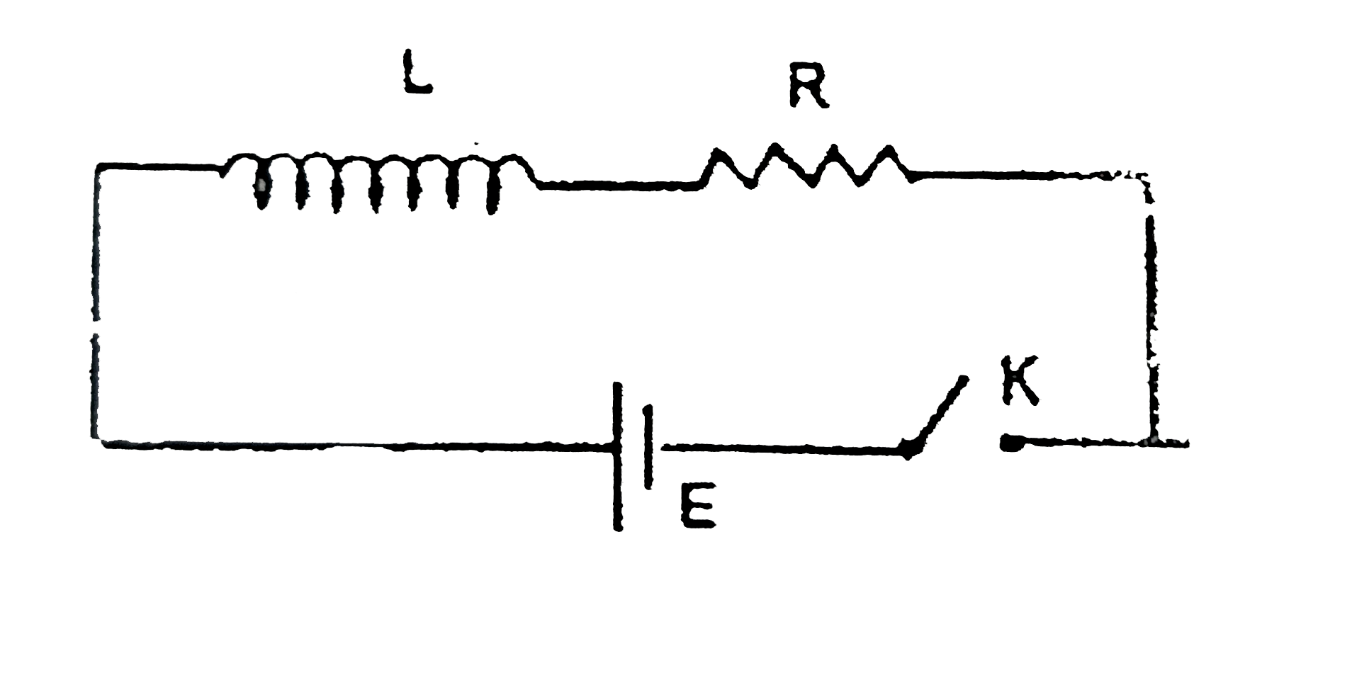
Shown in the figure is an R−L circuit. Just after the key (K) is closed
 Athe current in the circuit is zeroBpotential drop across the resistor is zeroCemf developed across the inductor equals the emf of the batteryDno heat is dissipated in the circuit
A potentiometer PQ is set up to comapre two resistances as shown in the figure. The ammeter A in the circuit reads 1.0 A when two way key K3 is open. The balance point is at a length l2 cm from P when two way key K3 is plugged in between 2 and 1, while the balance point is at a length l2 cm from P when key K3 is plugged in between 3 and 1. The ratio of the two resistance R1R2, is found to be-

View SolutionFor the arrangement of the potentimeter shown in the figure, The balance point is obtained at a distance 75cm from A when the key k is open
The second balance point is obtained at 60cm from A when the key k is closed. Find the internal resistance of the battery E1.

View SolutionA potentiometer circuit is setup as shown. The potential gradient across the potentiometer wire is kvolt/cm and the ammeter present in the circuit reads. 1.0A When two-way key is switched off. The balance point, when the key between the terminals (i) 1 and 2 (ii) 1 and 3, is plugged in, are found to be at lengths l2cm and l2cm respectively. The magnitudes, of the resistors R and X, in ohm, are then, equal, respectively, to

View SolutionShown in the figure is an R−L circuit. Just after the key (K) is closed

View SolutionFor the given circuit. Calculate reading of ammeter when key K is closed.

View Solution
