For the circuit shown in the figure

A
the current I through the battery is 7.5 mA.
B
the potential difference across RL is 18 V.
C
ratio of powers dissipated in R1andR2 is 3.
D
If R1andR2 are interchanged, magnitude of the power dessipated in R1 will decrease by a factor of 9
Text Solution
The correct Answer is:A

Equivalent resistance of the circuit can be calculated as follows:
R=R1+R2RLR2+RL=2+6×1.56+1.5=2+1.2=3.2kΩ
Hence current drawn from battery can be written as follows:
I=243.2×10³A=304mA=7.5mA
Hence, option (a) is correct
R2andRL are connected in parallel and hence current will be distributed inversely proportional to their resistances.
I1=66+1.5I=67.5×7.5=6mA
Hence, current through 6kΩ can be written as follows:
I2=I−I1=1.5mA
Potential difference across RL
=I1RL=(6×10⁻³)(1.5×10³)=9V
Hence option (b) is wrong
Power dissipated in R1
P1=I2R1=(7.5×10⁻³)2×(2×103)=0.1125Ω
Power dissipated in R2
P2=I22R2=(1.5×10⁻³)2×(6×103)=0.0135Ω
Hence, option (c) is wrong because P1/P2 is not equal to 3.
When R1andR2 are interchanged then the circuit will be reduced as shown in the figure:

Now equivalent resistance of the circuit can be calculated as follows:
R=R2+R1RLR1+RL=6+2×1.52+1.5=6+33.5=6+67=487kΩ
The current drawn from the battery can be calculated as follows:
I=24R=24487=3.5mA
Current through R1:
I2=1.52+1.5I=1.53.5×3.5=1.5mA
Power dissipation across R1:P1I22R1
=(1.5×10⁻³)2(2×10³)=4.5×10⁻³W
P1/P.1=25
Hence, option (d) is wrong.
|
Topper's Solved these Questions
- CURRENT ELECTRICITYBOOK - MODERN PUBLICATIONCHAPTER - CURRENT ELECTRICITYEXERCISE - Objective Type Questions (MULTIPLE CHOICE QUESTIONS) (C. MULTIPLE CHOICE QUESTIONS WITH MORE THAN ONE CORRECT ANSWER)
18 Videos
- CURRENT ELECTRICITYBOOK - MODERN PUBLICATIONCHAPTER - CURRENT ELECTRICITYEXERCISE - Objective Type Questions (MULTIPLE CHOICE QUESTIONS) (D. MULTIPLE CHOICE QUESTIONS BASED ON A GIVEN PASSAGE/COMPREHENSION)
15 Videos
- CURRENT ELECTRICITYBOOK - MODERN PUBLICATIONCHAPTER - CURRENT ELECTRICITYEXERCISE - Objective Type Questions (MULTIPLE CHOICE QUESTIONS) (B. MULTIPLE CHOICE QUESTION JEE (MAIN) & OTHER STATE BOARDS FOR ENGINEERING ENTRANCE)
45 Videos
- ATOMS BOOK - MODERN PUBLICATIONCHAPTER - ATOMS EXERCISE - Chapter Practice Test
16 Videos
- DUAL NATURE OF RADIATION AND MATTER BOOK - MODERN PUBLICATIONCHAPTER - DUAL NATURE OF RADIATION AND MATTER EXERCISE - CHAPTER PRACTICE TEST
15 Videos
Similar Questions
Knowledge Check
In the circuit shown in the figure
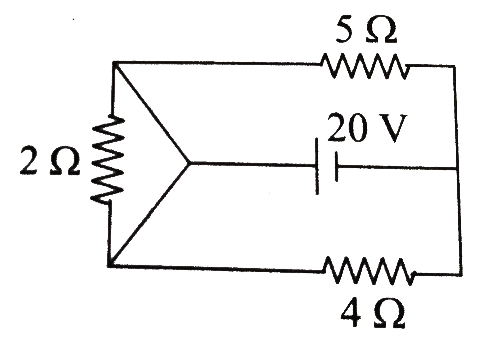 . Acurrent passing through 2Ω resistance is zero.Bcurrent passing through 4Ω resistance is 5ACcurrent passing through 5Ω resistance is 4A.Dpotential difference across 2Ω resistance is zero.
Consider the circuit shown in the figure
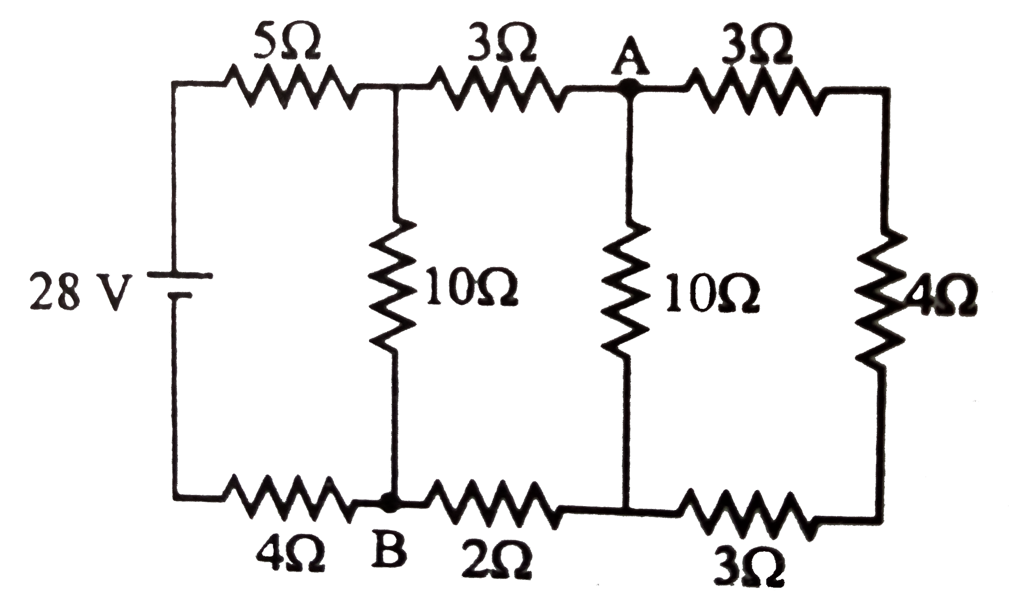 Athe current in the 5Ω resistor is 2ABthe current in the 5Ωresistor is 1ACthe potential difference VA−VB is 10VDthe potential difference VA−VB is 5V
The natural frequency of the circuit shown in the figure is
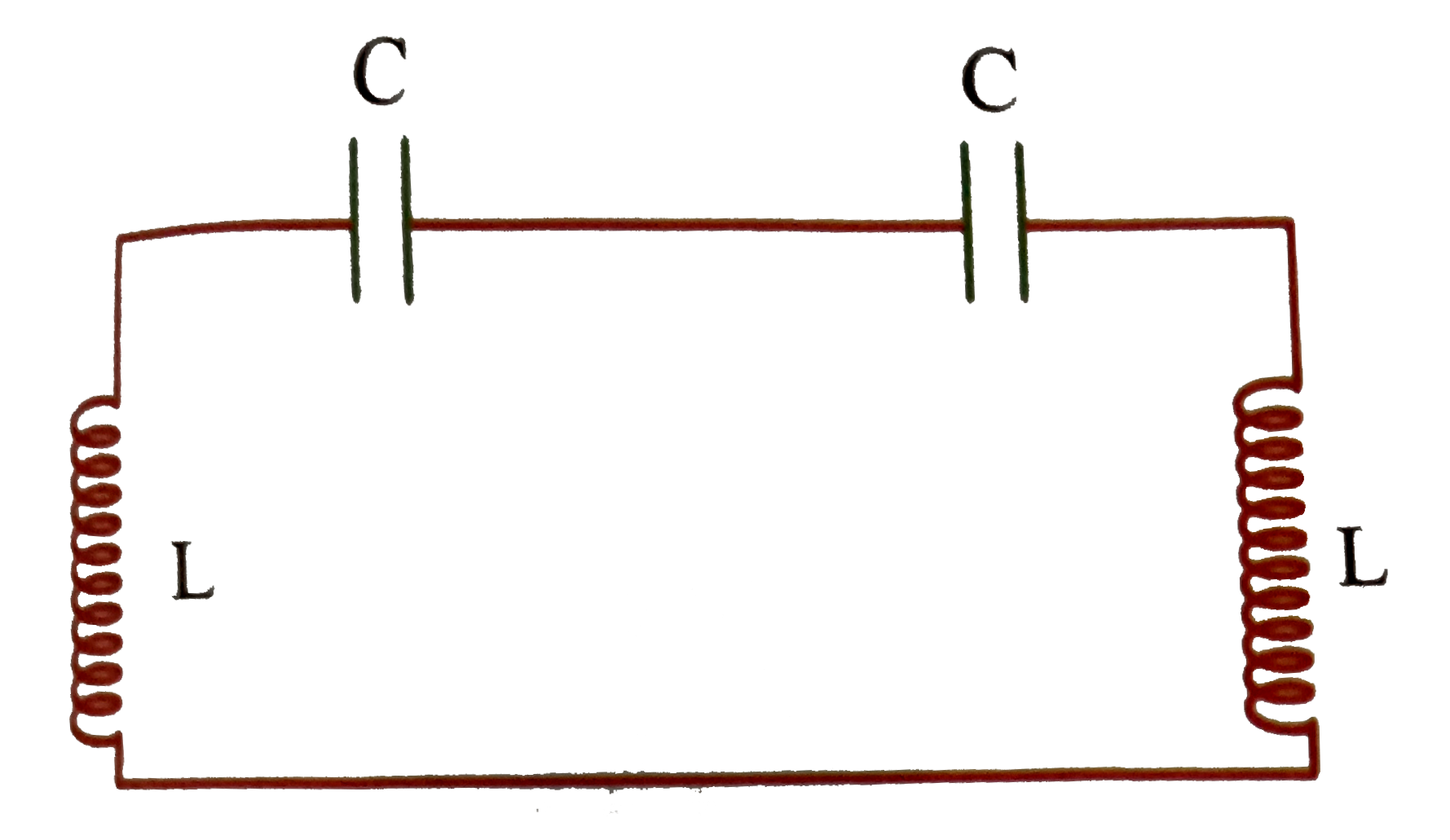 A12π√LCB1π√LCC2π√LCDnone
In the circuit shown in the figure
 .
.
View SolutionThe power factor of the circuit shown in the figure is
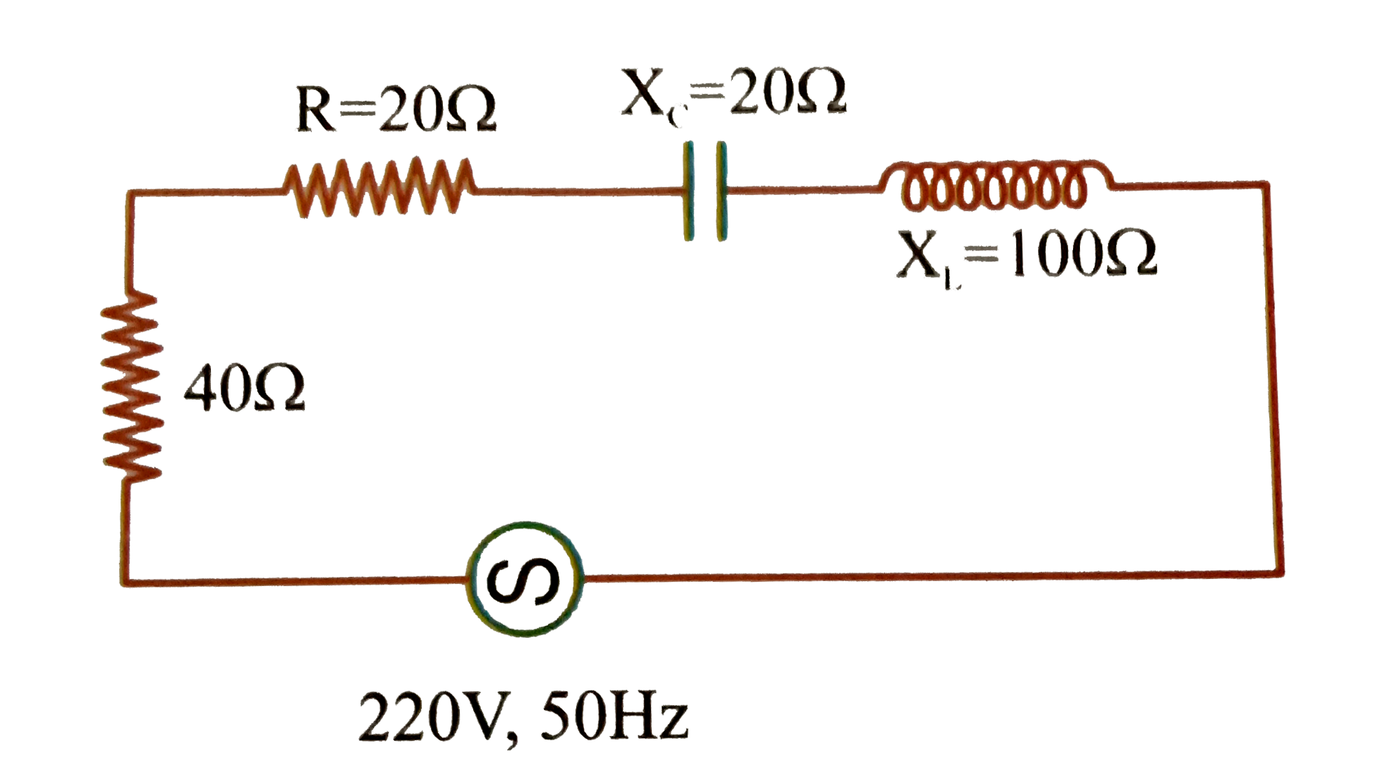
View SolutionThe natural frequency of the circuit shown in the figure is

View SolutionThe time constant of the circuit shown in the figure is
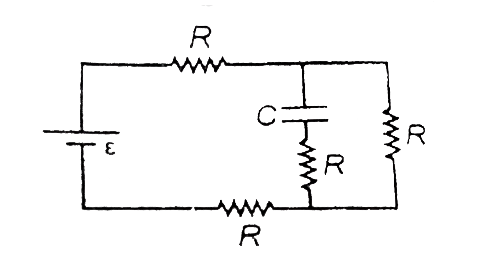
View SolutionThe power factor of the circuit shown in the figure is

View Solution

