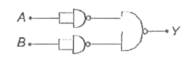
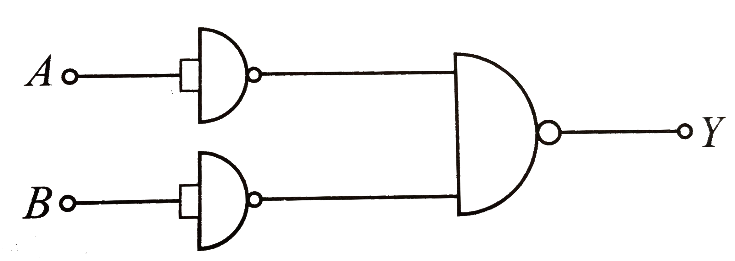
The outputs of two NOT gates are NORed, as shown in figure. What is this combination equivalent to?

Text Solution
From the logic circuit it follows that the output
y==A+=B
Applying DeMorgan.s first theorem,
We get,y==A.=B=AB
Hence given logic circuit is AND operation.
|
Topper's Solved these Questions
- SEMI-CONDUCTORS ELECTRONICSBOOK - OSWAAL PUBLICATIONCHAPTER - SEMI-CONDUCTORS ELECTRONICSEXERCISE - TOPIC -4 LOGIC GATES (SHORT ANSWER TYPE QUESTIONS-II)
2 Videos
- Sample Paper 8BOOK - OSWAAL PUBLICATIONCHAPTER - Sample Paper 8EXERCISE - Exercise
37 Videos
- SOLVED PAPER (II PUC JULY 2016)BOOK - OSWAAL PUBLICATIONCHAPTER - SOLVED PAPER (II PUC JULY 2016)EXERCISE - PART D
11 Videos
Similar Questions
Knowledge Check
The output Y of the gate circuit shown in the figure below is
 A¯¯¯¯¯¯¯¯A.BB¯¯¯A.¯¯¯BC¯¯¯¯¯¯¯¯¯¯¯¯¯¯¯¯A.BD¯¯¯A+¯¯¯B
The output Y of the gate circuit shown in the figure below is
 A¯¯¯¯¯¯¯¯A.BB¯¯¯A.¯¯¯BC¯¯¯¯¯¯¯¯¯¯¯¯¯¯¯¯A.BD¯¯¯A+¯¯¯B
The output of the combination of the gates shown in the figure below is
 .AA+A.BB(A+B)A+¯¯¯BC(A.B)+(¯¯¯A.¯¯¯B)D(A+B)(¯¯¯¯¯¯¯¯A.B)
Output Y of the gate shown in figure

View SolutionFigure shows a combination of logic gates. To what single gate is this combination equivalent?

View SolutionThe combination of the gates as shown in figure represent

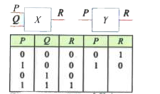
View SolutionLogic gates X and Y have the truth tables shown below

When the output of X is connected to the input of Y, the resulting combination is equivalent to a single.
View SolutionThe combination of NAND gates is shown in figure. The equivalent circuit is

View Solution


