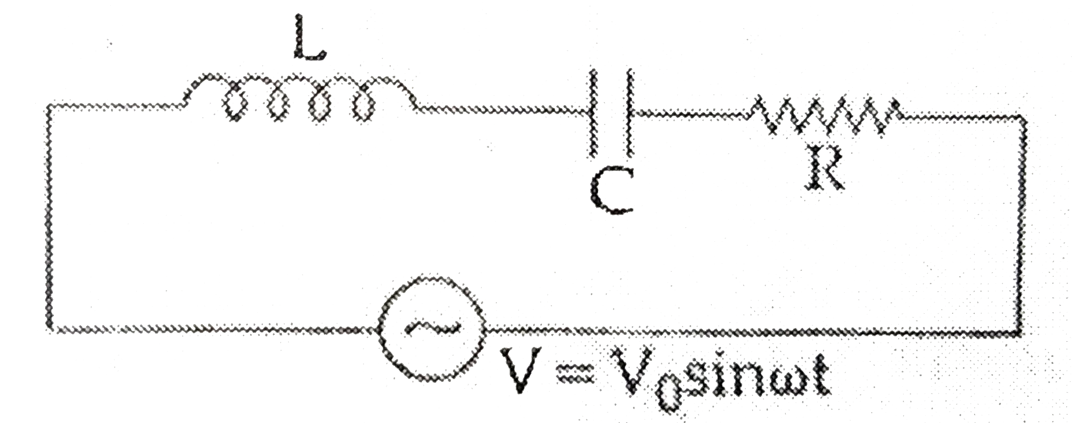
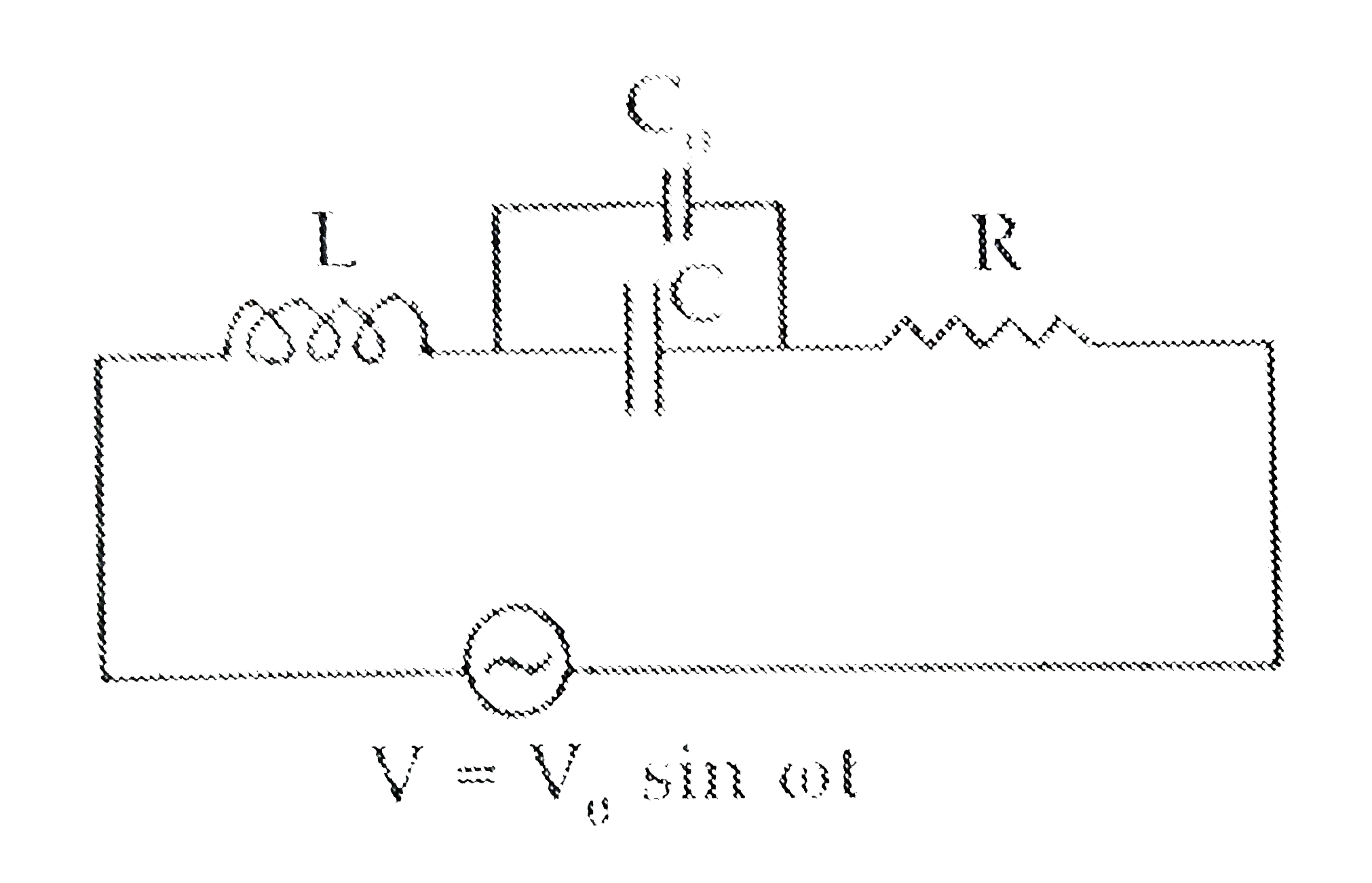
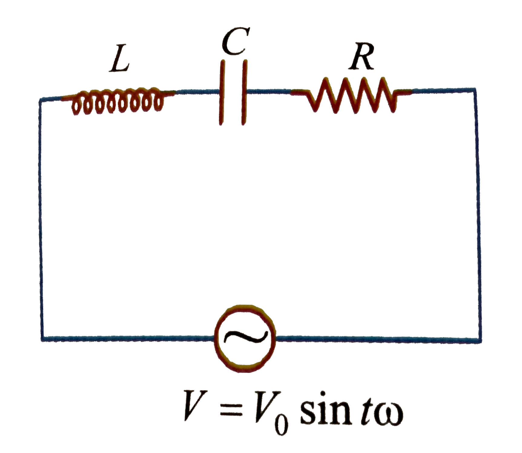
The current in the LCR circuit shown in the figure is observed to lead the voltage in phase. Without making any other change in the circuit, a capacitor, of capacitance C0 is (appropriately) joined to the capacitor C. This results in making the current, in the joined to the capacitor C. This results in making the current, in the modified' circuit, flow in phase with the applied voltage.
Draw a diagram of the modified circuit and obtain an expression of C0 in terms of Ω, L and C.
Net capacitance =C0+C
In resonance =XL=XC
ΩlL=1Ω(C+c0)
Ω2L=1C+C0
C+C0=1Ω2L
C01Ω2L−C
Topper's Solved these Questions
- BOOK - XII BOARDS PREVIOUS YEARCHAPTER - XII BOARDSEXERCISE - C.B.S.E.CLASS-XII PHYSICS (THEORY) [SET-I] (SECTION-A)5videos
XII BOARDS
- BOOK - XII BOARDS PREVIOUS YEARCHAPTER - XII BOARDSEXERCISE - SECTIONS-B6videos
XII BOARDS
- BOOK - XII BOARDS PREVIOUS YEARCHAPTER - XII BOARDSEXERCISE - SECTION-C55videos
XII BOARDS
- BOOK - XII BOARDS PREVIOUS YEARCHAPTER - SAMPLE PAPER 2019EXERCISE - SECTION D6videos
SAMPLE PAPER 2019
Similar Questions
(i) Find the value of the phase difference between the current and the voltage in the series LCR circuit shown below. Which one leads in phase : current or voltage ?
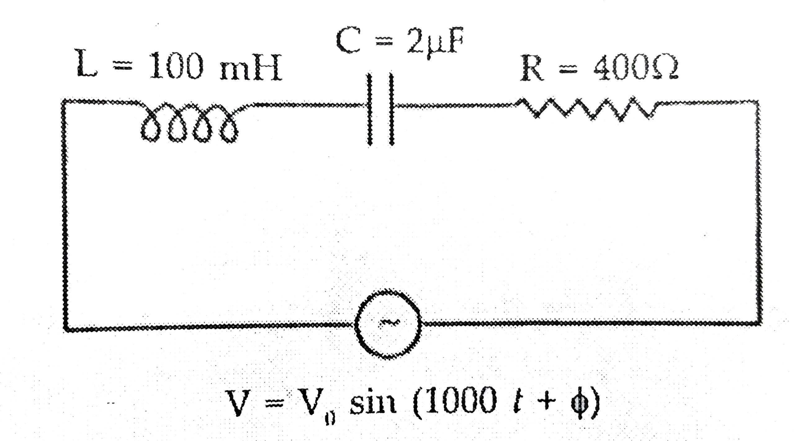
(ii) What making any other change, find the value of the additional capacitor C, to be connected in parallel with the capacitor C, in order to make the power factor of the circuit unity.View SolutionShow that the current leads the voltage in phase by π/2 in an AC circuit containing an ideal capacitor .
View Solution
Knowledge Check
- Question 1 - Select One
In the circuit shown in the figure, the total charge is 750μC and the voltage across capacitor C2 is 20 V. Then the charge on capacitor C2 is:
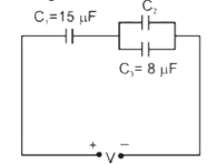 A650μCB450μCC590μCD160μC
 - Question 2 - Select One
For the LCR circuit, shown here, the current is observed to lead the applied voltage. An additional capacitor C', when joined with the capacitor C present in the circuit, makes the power factor of the circuit unity. The capacitor C' must have been connected in:
 Aseries with C and has magnitude C(ω2LC−1)Bseries with C and has a magnitde 1−ω2LCω2LCparallel with C and has a magnitude 1−ω2LCω2LDparallel with C and has a magnitude C(ω2LC−1)
 - Question 3 - Select One
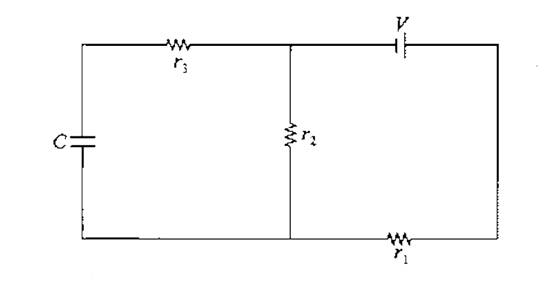
In the circuit shown in figure, the final voltage drop across the capacitor C is :
 AVr1r1+r2BVr2r1+r2CV(r1+r2)r2DV(r2+r1)r1+r2+r3
In a series CR circuit shown in figure,the applied voltage is 10V and the voltage across capacitor is found to be 8V
View SolutionA resistor, a capacitor of 100μF capacitance and an inductor are in series with on AC source of frequency 50Hz. If the current in the circuit is in phase with the applied voltage. The inductance of the inductor is
View SolutionA resistor 10Ω, a capacitor of 100μF capacitance and an inductor are in series with on AC source of frequency 50Hz. If the current in the circuit is in phase with the applied voltage. The inductance of the inductor is
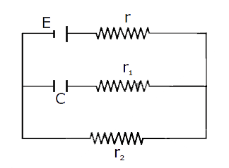
View SolutionIn the given circuit diagram when the current reaches steady state in the circuit , the charge on the capacitor of capacitance C will be :
 View Solution
In a LCR series circuit, if the phase difference between applied voltage and current is zero then
View Solution

