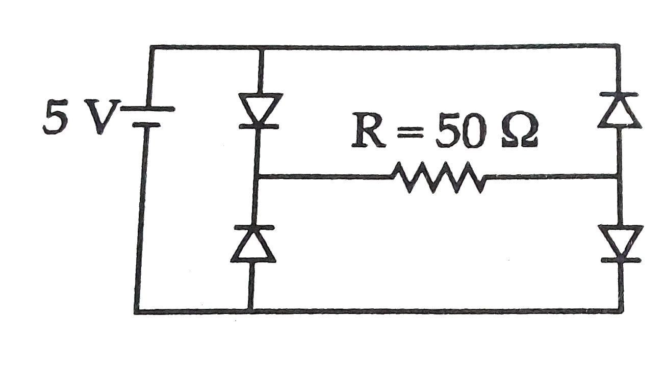
" Four silicon diodes are connected as shows in fig Assuming the diodes to be ideal The current through the resister is "
Video Solution
|
Answer
Step by step video & image solution for " Four silicon diodes are connected as shows in fig Assuming the diodes to be ideal The current through the resister is " by Physics experts to help you in doubts & scoring excellent marks in Class 12 exams.
Updated on:21/07/2023
Similar Questions
Knowledge Check
- Question 1 - Select One
In Fig.assuming the diode to be ideal
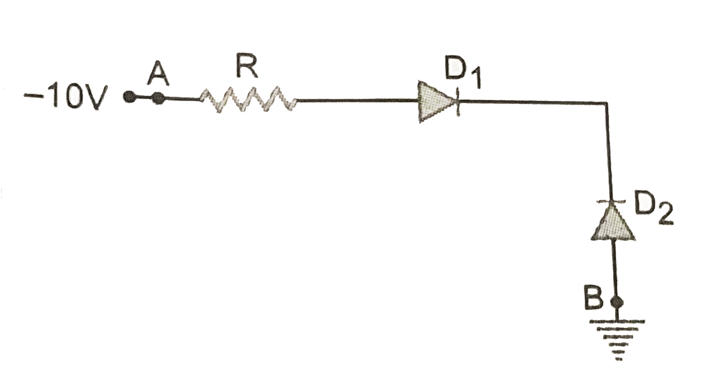 AD1 is forward biased and D2 is reverse biased and hence current flows from A to BBD2 is forward biased and D1 is reverse biased and hence no current flows from B to A and vice versaCD1 and D2 are both forward biased and hence current flows from A to BDD1 and D2 are both reverse biased and hence no current flows from A to B and vice versa
 - Question 2 - Select One
In figure , assuming the diodes to be ideal ,
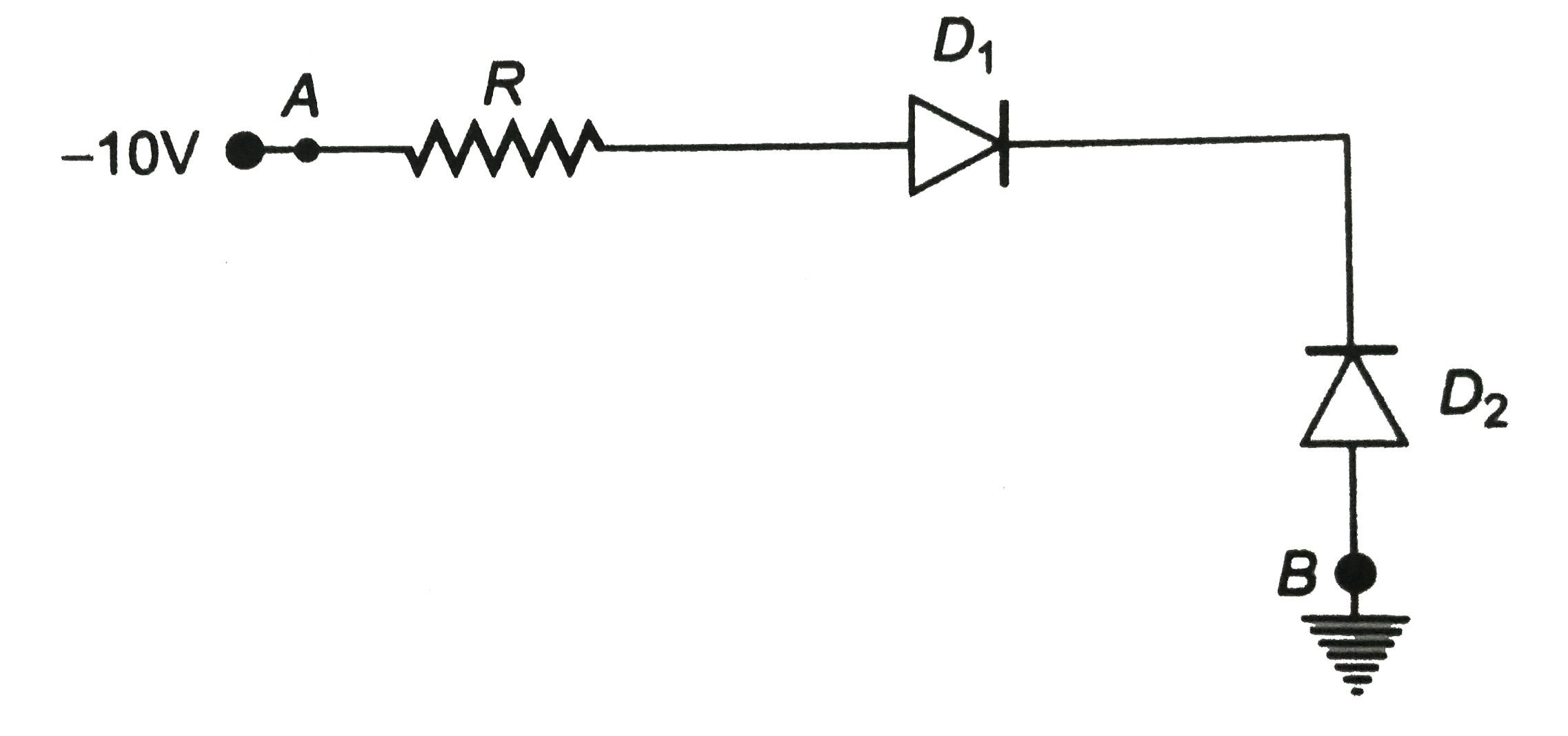 A(a) D1 is forward biased and D2 is reverse biased and hence current flows from A to B.BD2 is forward biased and D1 is reverse biased and hence no current flows from B to A and vice - versa.CD1 and D2 are both forward biased and hence current flows from A to B.DD1 and D2 are both reverse biased and hence no current flows from A to B and vice versa.
 - Question 3 - Select One
In Figure, assuming the diodes to be ideal,
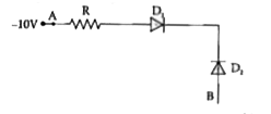 AD1 is forward biased and D2 is reverse biased and hence current flows from A to BBD2 is forward biased and D1 is reverse biased and hence no current flows from B to A and vice versa.CD1 and D2 are both forward biased and hence current flows from A to B.DD1 and D2 are both reverse biased and hence no current flows from A to B and vice versa.
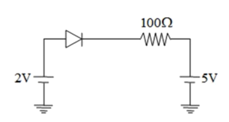
Assuming that the junction diode is ideal the current through the diode is :-
_E01_333_Q01.png) View Solution
View SolutionAssuming that the junction diode is ideal the current through the diode is :-
_E01_333_Q01.png) View Solution
View SolutionCurrent through the ideal diode is -
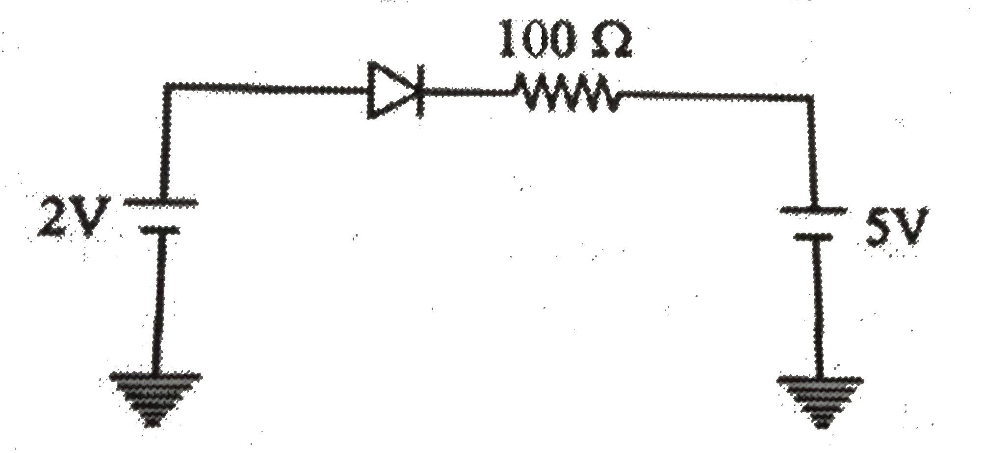 View Solution
In a figure given alongside assuming the diodes to be ideal
 View Solution
The given circuit has two ideal diodes connected as show in the figure. The current flowing through the resistance R1 will be
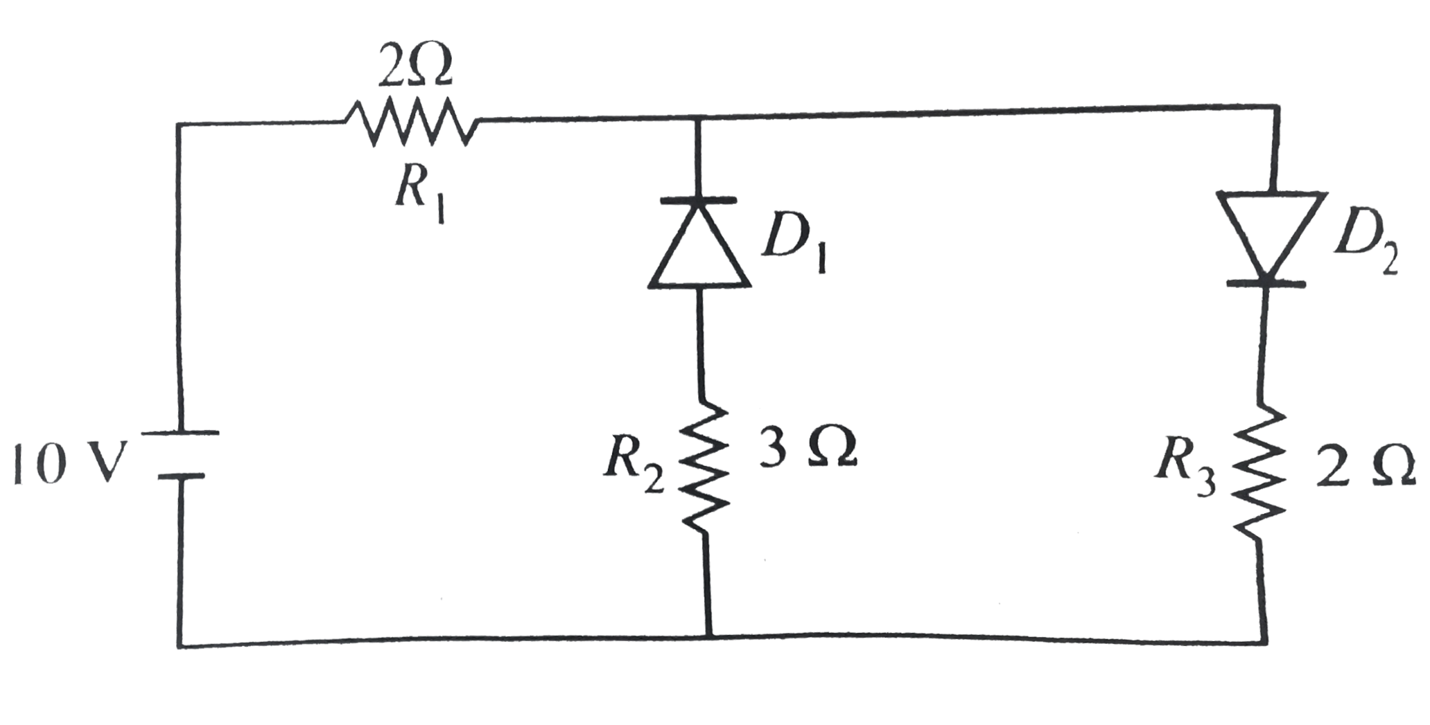 View Solution

