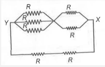
The equivalent resistance between X and Y in the circuit shows is

A
B
C
D
Text Solution
The correct Answer is:C
Let the distribution of current in the various arms be as shown in figure.

If R is the effective resistance between X and Y, then
Applying Kirchhoff.s second law in a cloesd loop XABCDYX, we get
or
Applying Kirchhoff.s second law in a closed loop ABEFA, we get
or
Applying Kirchhoff.s second law in a closed loop BCDEB, we get
or
or
From equations (iii) and (iv), we get
From equation (iii), we get
Substituting the value of in equation (i), we get
Substituting the value of in equation (ii), we get
From equations (v) and (vi), we get
|
Topper's Solved these Questions
- CURRENT ELECTRICITY BOOK - MTG GUIDECHAPTER - CURRENT ELECTRICITY EXERCISE - CHECK YOUR NEET VITALS
16 Videos
- CURRENT ELECTRICITY BOOK - MTG GUIDECHAPTER - CURRENT ELECTRICITY EXERCISE - MCQs AIPMT / NEET
32 Videos
- CURRENT ELECTRICITY BOOK - MTG GUIDECHAPTER - CURRENT ELECTRICITY EXERCISE - MCQs AIPMT / NEET
32 Videos
- ATOMS AND NUCLEIBOOK - MTG GUIDECHAPTER - ATOMS AND NUCLEIEXERCISE - AIPMT/NEET(MCQs)
40 Videos
- DUAL NATURE OF MATTER AND RADIATION BOOK - MTG GUIDECHAPTER - DUAL NATURE OF MATTER AND RADIATION EXERCISE - AIPMT/ NEET MCQs
30 Videos
Similar Questions
Knowledge Check
The equivalent resistance between x and y in the circuit shown is
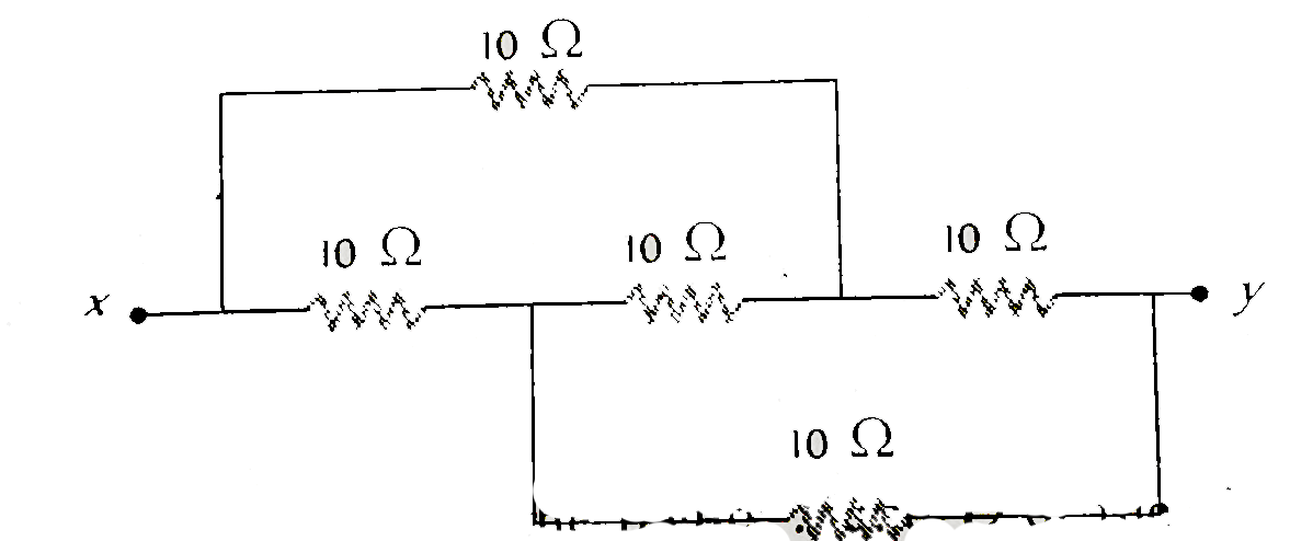 A10ΩB40ΩC20ΩD52Ω
The equivalent resistance between A and B for . the circuit shown in this figure is
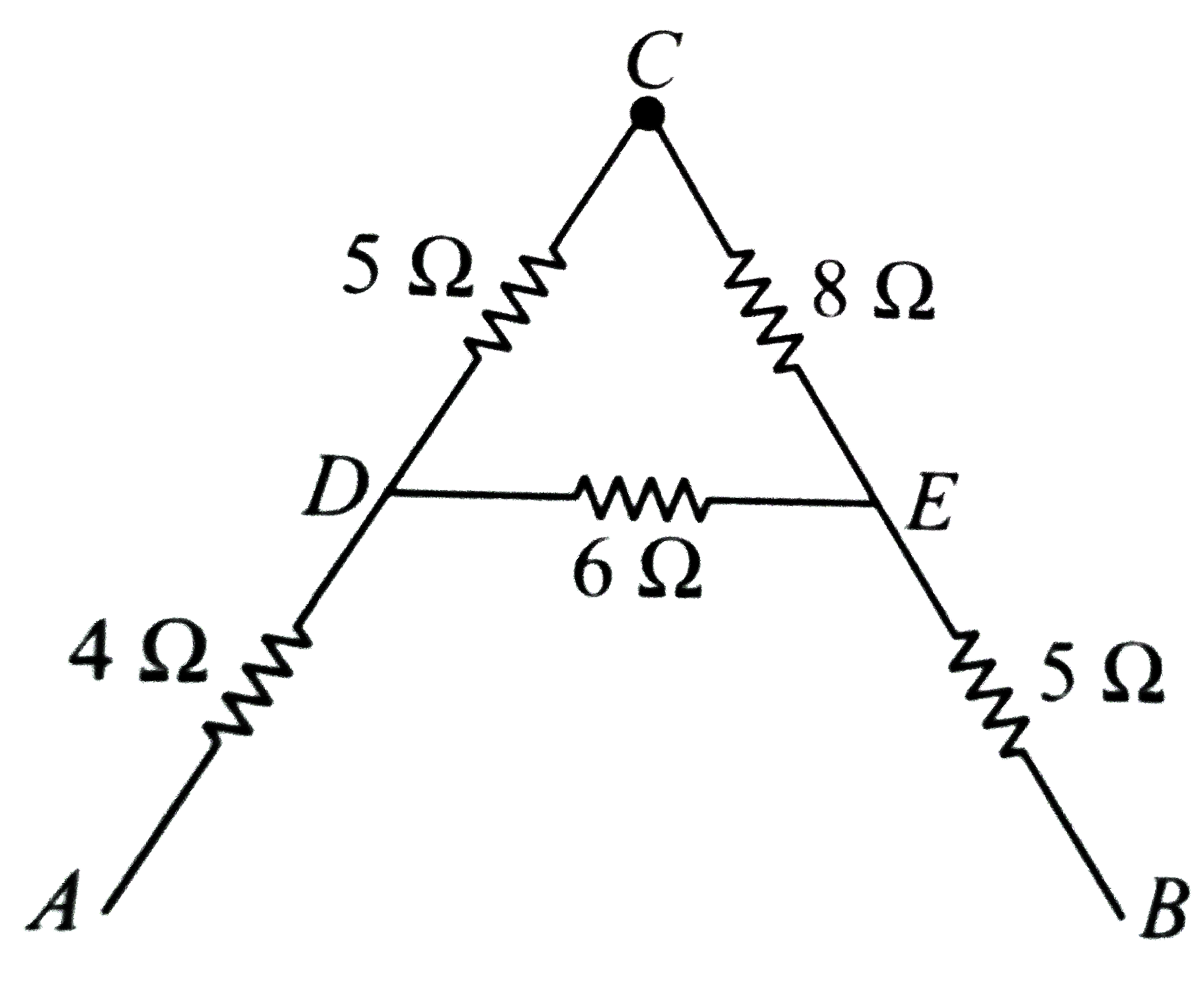 A13.1ΩB15.1ΩC17.1ΩD19.1Ω
The equivalent resistance between A and B for . the circuit shown in this figure is
 A13.1ΩB15.1ΩC17.1ΩD19.1Ω
The equivalent resistance between A and B in the given circuit is:
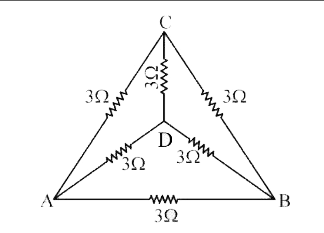
View SolutionThe equivalent resistance between A and B in the given circuit is:

View SolutionCalculate equivalent resistance between A and B of the circuit shown in fig.
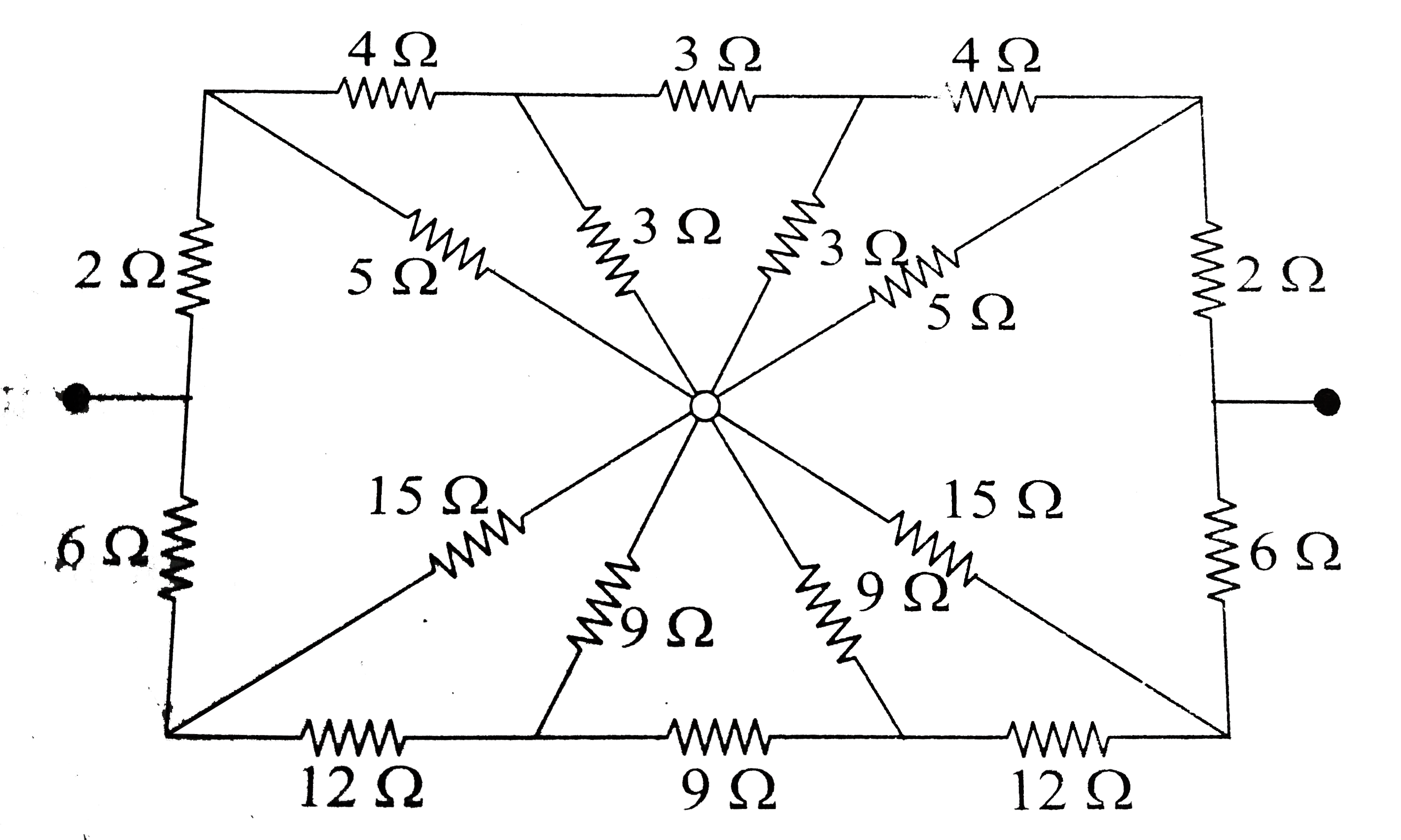
View SolutionWhat is the equivalent resistance between point A and C in the circuit shown in fig. ?

View SolutionCalculate equivalent resistance between A and B of the circuit shown in fig.

View Solution

_PHY_E05_041_Q01.png)