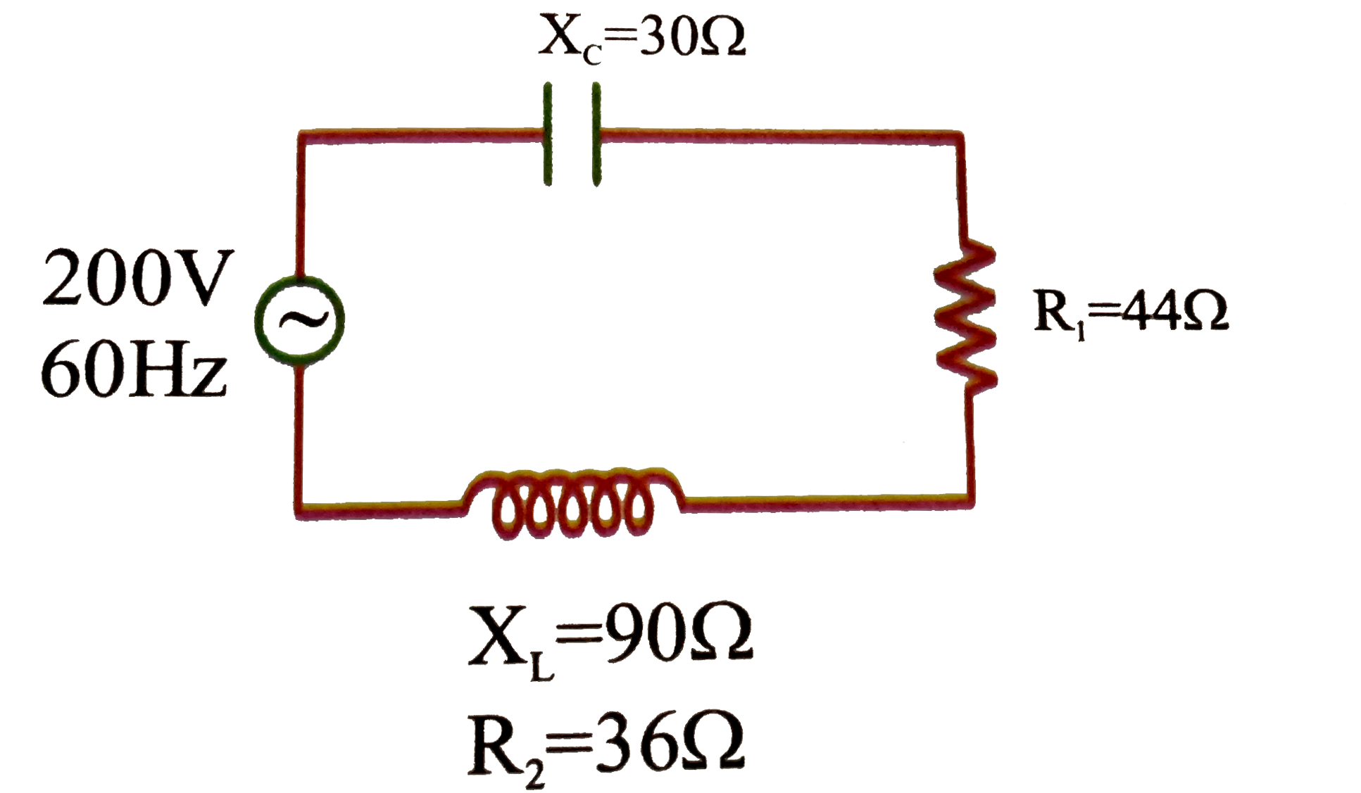
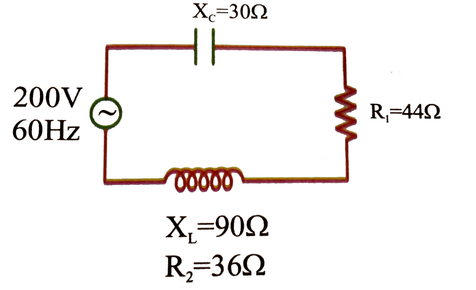
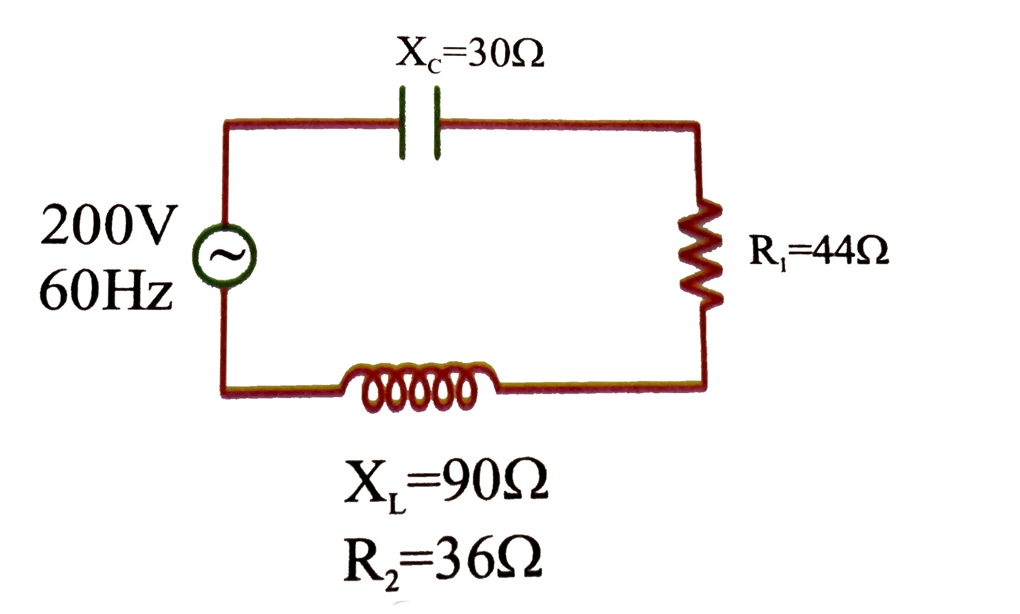
As given in the figure, a series circuit connected across a 200 V, 60 Hz line consists of a capacitor of capacitive reactance 30Ω, a non-inductive resistor of 44Ω, and a coil of inductive reactance 90 Ω and resistance 36Ω. The power dissipated in the coil is

320W
176W
144W
0 W
The correct Answer is:C

Impedance of the circuit , Z=√(R1+R2)2+(XL−XC)2
=√(44+36)2+(90−30)2=√(80)2+(60)2=100Ω
Current in the circuit , I=VZ=200V100Ω=2A
Power dissipated in the coil =I2R2=(2A)2(36Ω)=144W
Topper's Solved these Questions
- ELECTROMAGNETIC INDUCTION AND ALTERNATING CURRENTSBOOK - MTG GUIDECHAPTER - ELECTROMAGNETIC INDUCTION AND ALTERNATING CURRENTSEXERCISE - NEET CAFE TOPICWISE PRATICE QUESTIONS (WATTLESS CURRENT)
1 Videos
- ELECTROMAGNETIC INDUCTION AND ALTERNATING CURRENTSBOOK - MTG GUIDECHAPTER - ELECTROMAGNETIC INDUCTION AND ALTERNATING CURRENTSEXERCISE - NEET CAFE TOPICWISE PRATICE QUESTIONS (AC GENERATOR AND TRANSFORMER)
14 Videos
- ELECTROMAGNETIC INDUCTION AND ALTERNATING CURRENTSBOOK - MTG GUIDECHAPTER - ELECTROMAGNETIC INDUCTION AND ALTERNATING CURRENTSEXERCISE - NEET CAFE TOPICWISE PRATICE QUESTIONS (SERIES LR AND CR CIRCUITS)
1 Videos
- DUAL NATURE OF MATTER AND RADIATION BOOK - MTG GUIDECHAPTER - DUAL NATURE OF MATTER AND RADIATION EXERCISE - AIPMT/ NEET MCQs
30 Videos
- ELECTROMAGNETIC WAVESBOOK - MTG GUIDECHAPTER - ELECTROMAGNETIC WAVESEXERCISE - AIPMT/NEET(MCQs)
15 Videos
Similar Questions
As given in the figure, n series circuit coanected across a 200V60HZ line coasists of a capacitor of capacitive reactance 30ohm, sa non-inductive resistar of 44ohm, and a coil of inductive reactance 90ohm and resistance 36ohm. The power dissipated (in watt) in the coil is
'(##CEN_KSR_PHY_JEE_C24_E01_021_Q11##)'
View SolutionA series circuit connected across a 200V,60Hz line consists of a capacitive reactance 30Ω non inductive resistor of 44Ω and a coil of inductive reactance 90Ω and resistance 36Ω as shown in the diagram

The power dissipated in the inductance coil is
View Solution
Knowledge Check
As given in the figure a series circuit connected across a 200 V, 60 Hz line consists of a capacitor of capacitive reactance 30Ω , a non-inductive resistor 44Ω , a coil of inductive reactance 9012 and another resistance of resistance 36Ω. The power dissipated in the circuit is
 A320 WB176 WC144 WD0 W
A series circuit connected across a 200V,60Hz line consists of a capacitive reactance 30Ω non inductive resistor of 44Ω and a coil of inductive reactance 90Ω and resistance 36Ω as shown in the diagram

The power dissipated in the inductance coil isAzeroB320WC144WD160WA series circuit connected across a 200V,60Hz line consists of a capacitive reactance 30Ω non inductive resistor of 44Ω and a coil of inductive reactance 90Ω and resistance 36Ω as shown in the diagram

The power used in the circuit isA320WB144WC160WD96W
A inductor of reactance 1Ω and a resistor of 2Ω are connected in series to the terminals of a 6 V (rms) a.c. source. The power dissipated in the circuit is
View SolutionA series circuit connected across a 200V,60Hz line consists of a capacitive reactance 30Ω non inductive resistor of 44Ω and a coil of inductive reactance 90Ω and resistance 36Ω as shown in the diagram

The potentail difference across the coil is
View SolutionA circuit consists of a noniductive resistor of 50Ω, a coil of inductance 0.3H and resistance 2Ω, and a capacitor of 40μF in series and is supplied with 200 volt rms at 50 cycles / sec. Then
View SolutionAn inductor of reactance 2Ω and a resistor of 4Ω are connected in series to the terminals of a 12 V (rms ) AC source. The power dissipated in the circuit is
View SolutionAn inductor of reactance 1 Ω and a resistor of 2 Ω are connected in series to the terminals of a 6 V (rms) a.c. source. The power dissipated in the circuit is
View Solution
