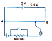
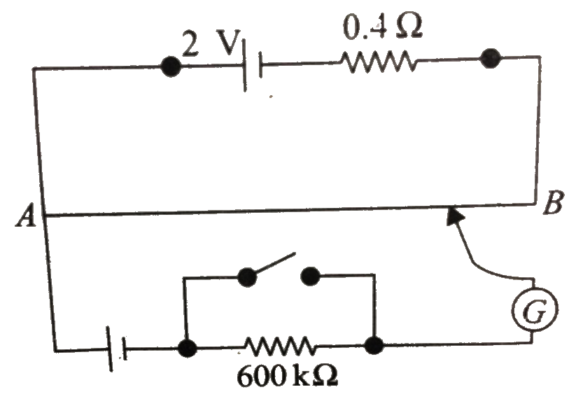
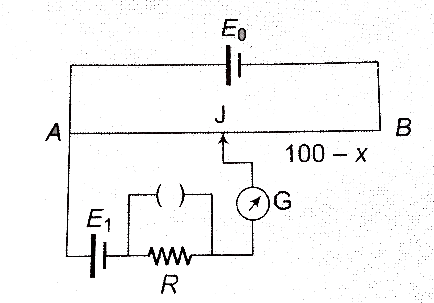
Figure shows a potentiometer with a cell of 2.0 V and internal resistance 0.40 Ω maintaining a potential drop across the resistor wire AB. A standard cell which maintains a constant emfof 1.02 V (for very moderate currents upto a few mA) gives a balance point at 67.3 cmlength of the wire. To ensure very low currents drawn from the standard cell, a very high resistance of 600 kΩ is put in series with it, which is shorted close to the balance point. The standard cell is then replaced bya cell of unknown emfe and the balance point found similarly, turns out to be at 82.3 cm length of the wire.

(a) What is the value ε ?
(b) What purpose does the high resistance of 600 KΩ have ?
(c) Is the balance point affected by this high resistance ?
(d) Would the method work in the above situation if the driver cell of the potentiometer had an emf of 1.0V instead of 2.0 V ?
(e) Would the circuit work well for determining an extremely small emf, say of the order of a few mV (such as the typical emf of a thermocouple) ? If not, how will you modify the circuit ?
(f) Can we use above circuit to measure very small emf of the order of mV. (For example, emf obtained in thermocouple) ? If not, then what change would you make ?
(a) We have ,
ε1ε2=l1l2
∴1.02ε=67.382.3
∴ε=1.02×82.367.3
∴ε=1.247 V
(b) Purpose of connecting high value resistance in secondary circuit is to reduce the current through the galvanometer (and hence to save the galvanometer from the possible damage) when movable contact (jockey) is far from the balancing point.
(c) No, because by connecting resistance in secondary circuit of a potentiometer, potential gradient existing on potentiometer wire does not change and so balancing length also does not change.
(d) Yes, because ε1=kl1=(ερR+Lρ+r)l1=
constant .
⇒ As r change , l1 has to change.
⇒ Balancing poin will be affected.
(e) No, because in order to obtain balancing point on the potentiometer wire, emf of driver cell (connected in primary circuit) must be greater than emf of unknown cell (connected in secondary circuit).
Note : See the explanation given below.
For primary circuit of a potentimeter,
I=εR+Lρ+r ... (1)
(Where ρ = resistance per unit length of a potentiometer wire )
According to formula of potential gradient,
k = ερR+Lρ+r=(εR+Lρ+r)ρ=Iρ.... (2)
If emf ε1 is balaned by length l1 of potentiometer wire then,
ε1=kl1
∴(ε1)max=K(l1)max= kL = L ρL .... (3)
From equation (1),
ε=IR+ILρ+Ir
∴ε=IR+(ε1)max+Ir
∴ε−(ε1)max=IR+Ir
∴ε−(ε1)max>0
∴ε>(ε1)max
above is the required result .
(f) In order to measure very small emf accurately, we require to have very small potential gradient on the potentiometer wire. Value of k can be reduced considerably by connecting proper series resistance with potentiometer wire. Also by increasing length of potentiometer wire, we can decrease the value of potential gradient.
Topper's Solved these Questions
- CURRENT ELECTRICITYBOOK - KUMAR PRAKASHANCHAPTER - CURRENT ELECTRICITYEXERCISE - SECTION [B] (NUMERICAL FROM .DARPAN. BASED ON TEXTBOOK)
13 Videos
- CURRENT ELECTRICITYBOOK - KUMAR PRAKASHANCHAPTER - CURRENT ELECTRICITYEXERCISE - SECTION [B] (NUMERICAL)
10 Videos
- CURRENT ELECTRICITYBOOK - KUMAR PRAKASHANCHAPTER - CURRENT ELECTRICITYEXERCISE - SECTION [B] NUMERICALS (NUMERICAL FROM TEXTUAL ILLUSTRATIONS)
14 Videos
- BOARD'S QUESTION PAPER MARCH-2020 BOOK - KUMAR PRAKASHANCHAPTER - BOARD'S QUESTION PAPER MARCH-2020 EXERCISE - PART-B SECTION -C
4 Videos
- DUAL NATURE OF RADIATION AND MATTERBOOK - KUMAR PRAKASHANCHAPTER - DUAL NATURE OF RADIATION AND MATTEREXERCISE - Section-D (MCQs asked in GUJCET/Board Exam)
1 Videos
Similar Questions

Fig. shows a potentiometer with a cell of 2.0 V and internal resistance 0.40 Ω maintaining a potential drop across the resistor wire AB. A standard cell which maintains a constant emf of 1.02 V (for very moderate currents up to a few mA) gives a balance point at 67.3 cm length of the wire. To ensure very low currents drawn from the standard cell, a very high resistance of 600 kΩ is put in series with it, which is shorted close to the balance point. The standard cell is then replaced by a cell of unknown emf and the balance point found similarly, turns out to be at 82.3 cm length of the wire.
(a) What is the value of ε ? (b) What purpose does the high resistance of 600 kΩ have ? (c) Is the balance point affected by this high resistance ? (d) Would the method work in the above situation if the driver cell of the potentiometer had an emf of 1.0 V instead of 2.0 V? (e) Would the circuit work well for determining an extremely small emf, say of the order of a few mV (such as the typical emf of a thermo-couple) ? If not, how will you modify the circuit ?
View SolutionFigure 6.36 shows a potentiometer with a cell of emf 2.0V and internal resistance 0.4Ω maintaining a potential drop across the resistor wire AB. A standard cell that maintains a constant emf of 1.02V (for very moderate current up to emf μA) gives a balance point at 67.3cm length of the wire. To ensure very low current is drawn the standard cell, a very high resistance of 600kΩ is put in series with it, which is shorted close to the balance point. The standard cell is then replaced by a cell of unknown emf ε and the balance point found, similary, turns out to be at 82.3cm length of the wire.
a. What is the value of ε?
b.What purpose does the high resistance of 600kΩ have?
c. Is the balance point affected by this high resistance?
d. Is the balance point affected by internal resistance of the driver cell?
e. Would the method work in the above situation if the driver cell of the potentiometer had an emf of 1.0V instead of 2.0V?
f. Would the circuit work well for determining an extermely small emf, say of the order of a few mV (such as the typical emf of a thermocouple)? If not, how will you modify the circuit ?

View Solution
Knowledge Check
A cell of emf 2.0 V and internal resistance 0.1 Ω is connected with a resistance of 3.9Ω. The voltage across the cell terminals will be
A0.50 VB1.90 VC1.95 VD2.0 Vis made of uniform material and cross-sectional area, and it has uniform resistance per unit length. The potential gradient depends upon the current in the wire.
A potentiometer with a cell of emf 2V and internal resistance 0.4Ω is used across the wire AB. A standard cadmium cell of emf 1.02V gives a balance point at 66cm length of wire. The standard cell is then replaced by a cell of unknows emf e (internal resistance r), and the balance. Point found similarly turns out to be 88cm length of the wire. The length of potentiometer wire AB is 1m.
If the resistance is connected across the cell e, the balancing length willAincreasesBdecreaseCremain sameDnoneis made of uniform material and cross-sectional area, and it has uniform resistance per unit length. The potential gradient depends upon the current in the wire.
A potentiometer with a cell of emf 2V and internal resistance 0.4Ω is used across the wire AB. A standard cadmium cell of emf 1.02V gives a balance point at 66cm length of wire. The standard cell is then replaced by a cell of unknows emf e (internal resistance r), and the balance. Point found similarly turns out to be 88cm length of the wire. The length of potentiometer wire AB is 1m.
The reading of the potentiometer, if a 4V battery is used instead of e isA88.3cmB47.3cmC95cmDcannot be calculated
Figure 6.36 shows a potentiometer with a cell of emf 2.0V and internal resistance 0.4Ω maintaining a potential drop across the resistor wire AB. A standard cell that maintains a constant emf of 1.02V (for very moderate current up to emf μA) gives a balance point at 67.3cm length of the wire. To ensure very low current is drawn the standard cell, a very high resistance of 600kΩ is put in series with it, which is shorted close to the balance point. The standard cell is then replaced by a cell of unknown emf ε and the balance point found, similary, turns out to be at 82.3cm length of the wire.
a. What is the value of ε?
b.What purpose does the high resistance of 600kΩ have?
c. Is the balance point affected by this high resistance?
d. Is the balance point affected by internal resistance of the driver cell?
e. Would the method work in the above situation if the driver cell of the potentiometer had an emf of 1.0V instead of 2.0V?
f. Would the circuit work well for determining an extermely small emf, say of the order of a few mV (such as the typical emf of a thermocouple)? If not, how will you modify the circuit ?

View Solution
The figure shows a potentiometer using a cell E of emf 2.0V and internal resistance 0.40Ω connected to a resistor wire AB. A standard cell of constant emf of 1.02V gives a balance point a t 67.3cm length of the wire. A very high resistance R=100kΩ is put in with the standard cell. This resistance is shorted by inserting switch S when close to the balance point. The standard cell is then replaced by a cell of unknown emf E and the null point turns out to be 82.3cm length of the wire.
(a) What is the value of E ?
(b) What is the purpose of using the high resistance R ?
( c) Is the null point affected by this high resistance ?
(d) Is the null point affected by the internal resistance of the cell E ?
( e) Would this method work if
(i) the internal resistance of cell E were higher than the resistance of wire AB and
(ii) the emf of cell E were 1.0V instead of 2.0V ?
View SolutionA potentiometer with a cell of EMF 2V and internal resistance 0.4Ω is used across the wire AB. A standard cadmium cell of EMF 1.02V gives a balance point at 66cm length of wire. The standard cell is then replaced by a cell of unknows EMF e (internal resistance r), and the balance. Point found similarly turns out to be 88cm length of the wire. The length of potentiometer wire AB is 1m.
The value of e is
View SolutionIn a potentiometer circuit, the emf of driver cell is 2V and internal resistance is 0.5Ω. The potentiometer wire is 1m long . It is found that a cell of emf 1V and internal resistance 0.5Ω is balanced against 60 cm length of the wire. Calculate the resistance of potentiometer wire.
View SolutionIn a potentiometer circuit, the emf of driver cell is 2V and internal resistance is 0.5Ω. The potentiometer wire is 1m long . It is found that a cell of emf 1V and internal resistance 0.5Ω is balanced against 60 cm length of the wire. Calculate the resistance of potentiometer wire.
View Solution
