(a) In the figure given below the input waveform is converted into the output waveform by a device 'X'. Name the device and draw its circuit diagram.

(b) Identify the logic gate represented by the circuit as shown and write its truth table.

Step by step video & image solution for (a) In the figure given below the input waveform is converted into the output waveform by a device 'X'. Name the device and draw its circuit diagram. (b) Identify the logic gate represented by the circuit as shown and write its truth table. by Physics experts to help you in doubts & scoring excellent marks in Class 12 exams.
Updated on:21/07/2023Similar Questions
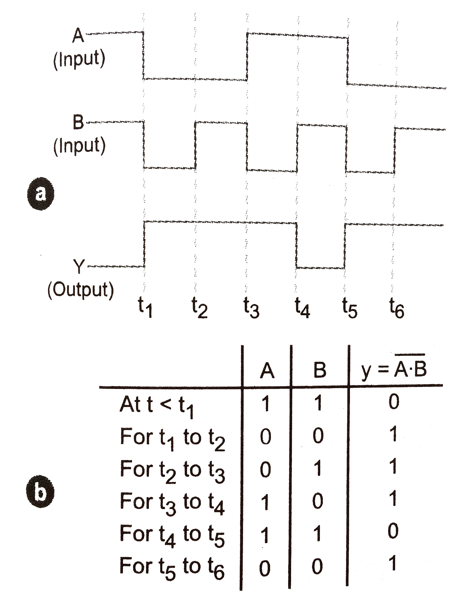
The following Fig. shows the input waveforms (A,B) and the output waveform (y) of a gate. Identify the gate and write its truth table.

View SolutionIdentify the logic gates marked P and Q in the circuit Fig. Write the truth table for this combination.

View SolutionIn the circuit shown in the figure, identify the equivalent gate of the circuit and make its truth table.

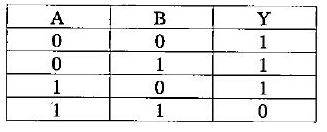
View SolutionIdentify the logic gate whose truth table is given below and draw its symbol :

View SolutionWrite the truth table of the following circuit. Name the gate represented by this circuit.

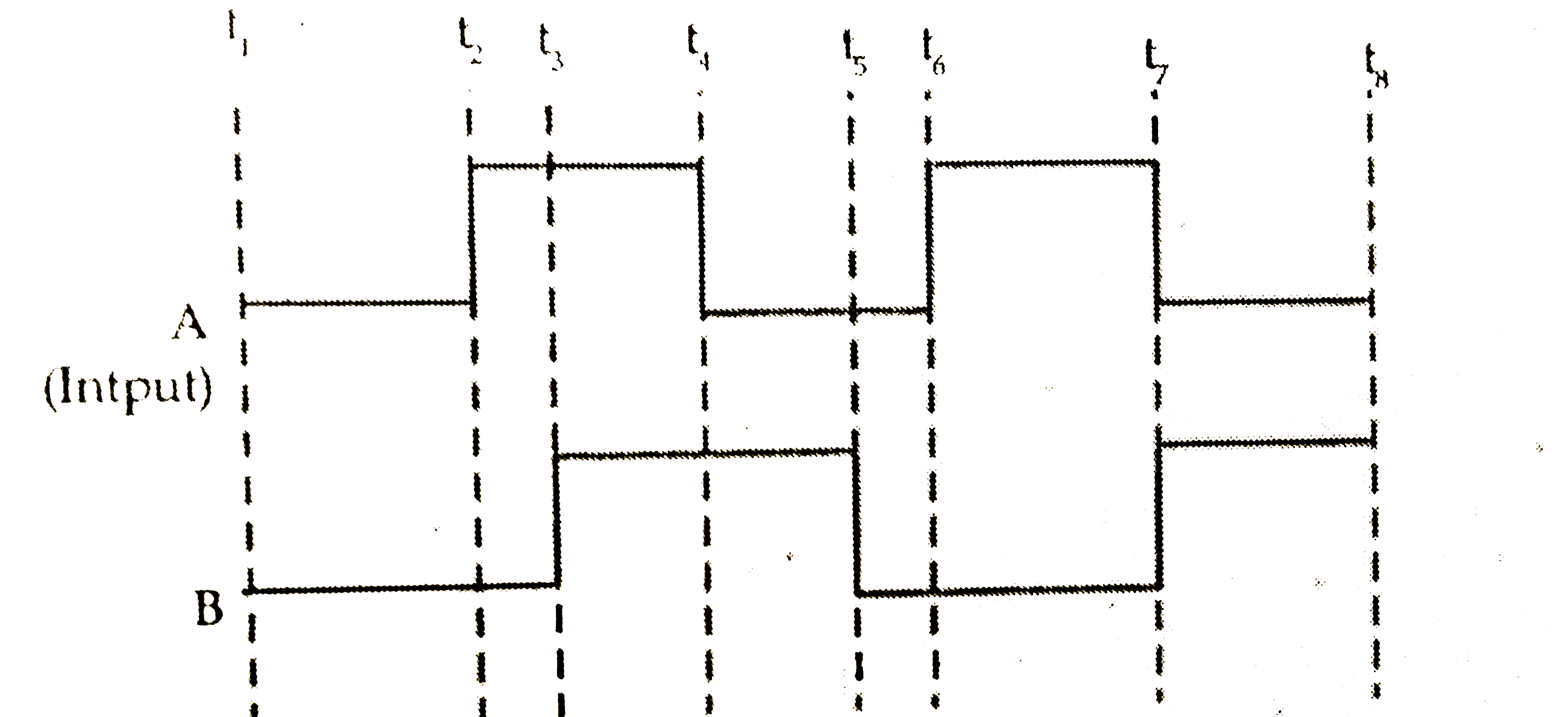
View SolutionUsing the wave forms of the input A and B, draw the output waveform of the given logic circuit . Identify the logic gate obtained . Write also the truth table.

View SolutionThe figure shows the input weveforms A and B for 'AND' gate Draw the output waveform and write the truth table for this logic gate
 .
.
View SolutionDraw the output waveform X, using the given inputs A and B for the logic circuit shows below. Also, identify the logic operation performed by this circuit.

View SolutionDraw the output waveformed at X, using the given inputs A and B for the logic circuit shows below. Also, identify the logic operation performed by this circuit.

View Solution(i) Figure shows the input waveform which is converted by a device .X. into an output wavefrom. Mane the device and explain its working using the proper circuit.
(ii) Draw the forward bias and reverse blas circuit for the basic component of the device and draw the characterstics.
Explain clearly which region of the curve is used in an amplifier.
View Solution
