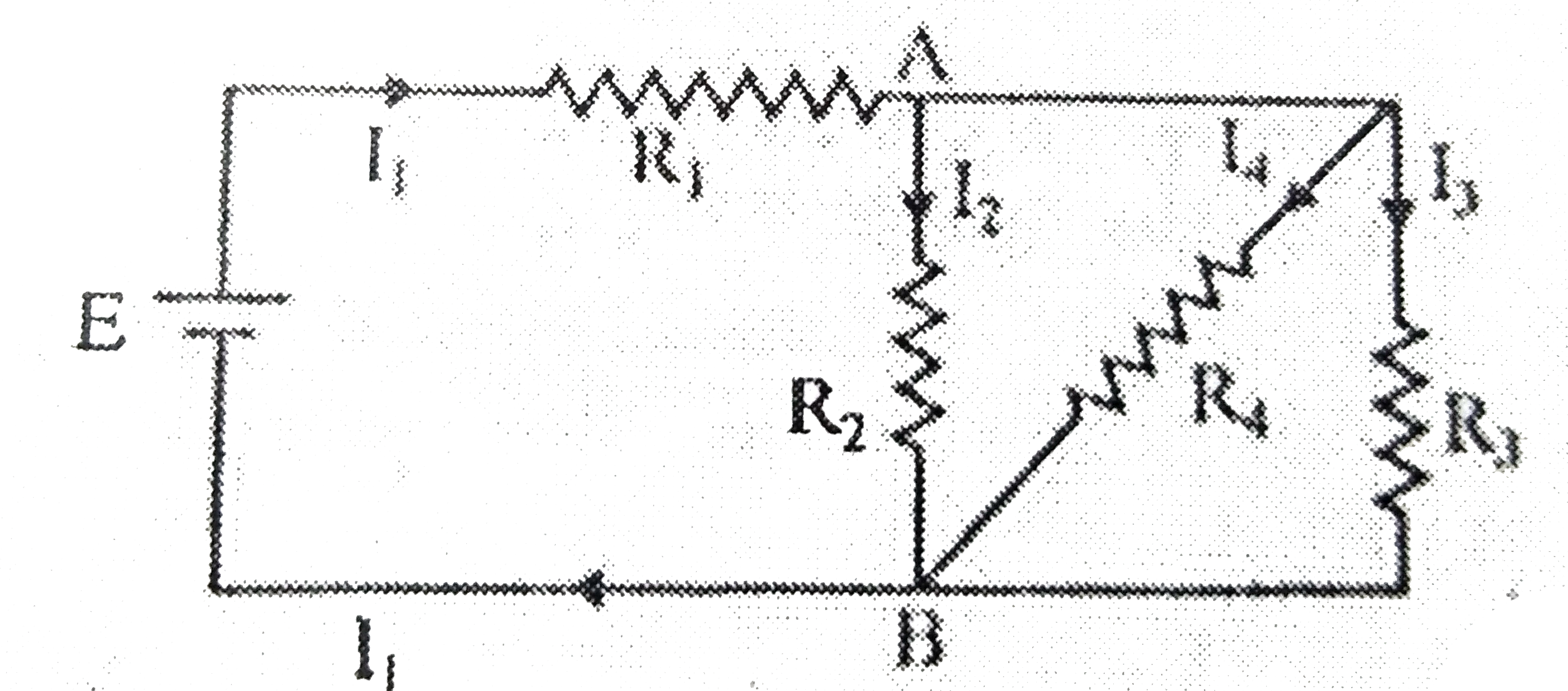
In the circuit shown, R1=4Ω,R2=R3=15Ω,R4=30ΩandE=10V. Caculate the equivalent resistance of te circuit and the current in each resistor.
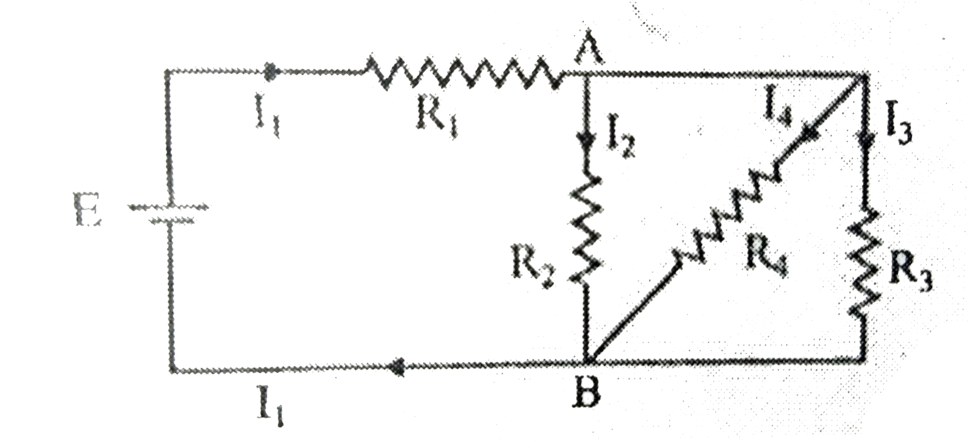
Step by step video & image solution for In the circuit shown, R_1=4Omega,R_2=R_3=15Omega,R_4=30OmegaandE=10V. Caculate the equivalent resistance of te circuit and the current in each resistor. by Physics experts to help you in doubts & scoring excellent marks in Class 12 exams.
Updated on:21/07/2023Similar Questions
Knowledge Check
For the circuit shown in the figure, the current in the 4Ω resistor is
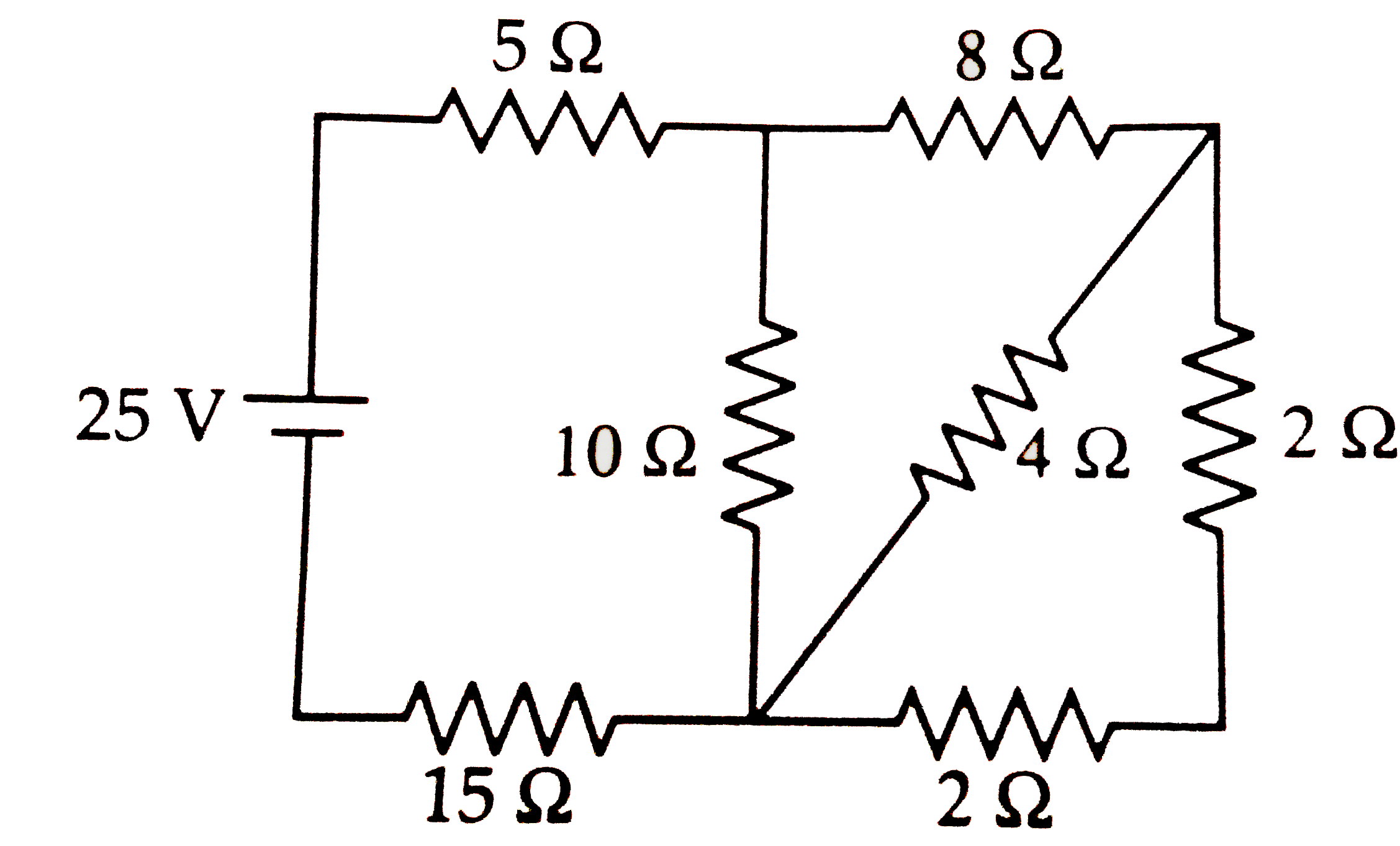 A0.5AB0.25AC1AD1.5A
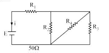
In the given circuit, E=8V,R1=1Ω,R2=R3=R4=5Ω.The current through the resistance R4 is (in A):
View Solution(a) Resistors given as R1,R2andR3 are connected in series to a battery V. Draw the circuit diagram showing the arrangement. Derive an expression for the equivalent resistance of the combination.
(b) If R1=10Ω,R2=20ΩandR3=30Ω, calculate the effective resistance when they are connected in series to a battery of 6 V. Also find the current flowing in the circuit.
View SolutionThe current in the resistor R3 in the circuit as shown in the figure is

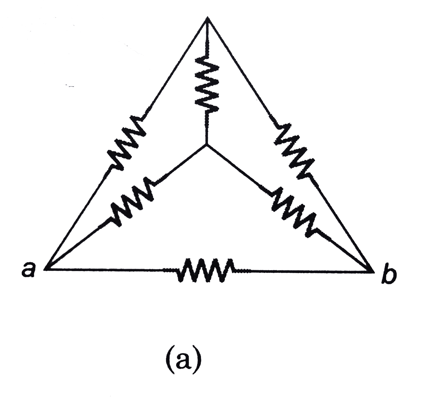
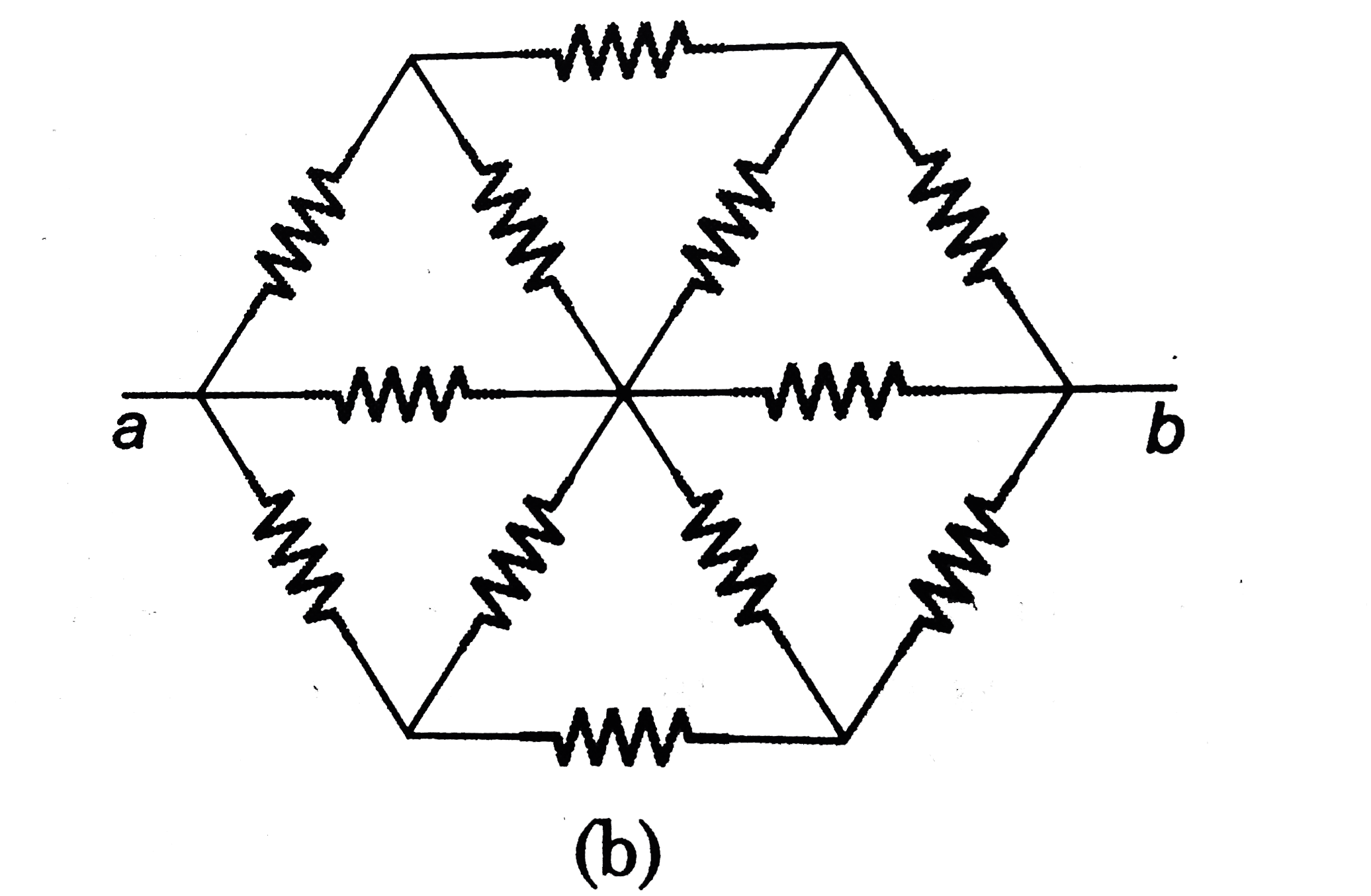
View SolutionFind the equivalent resistance of the circuit shown in figure between the points a and b.Each resistor has a resistances r.
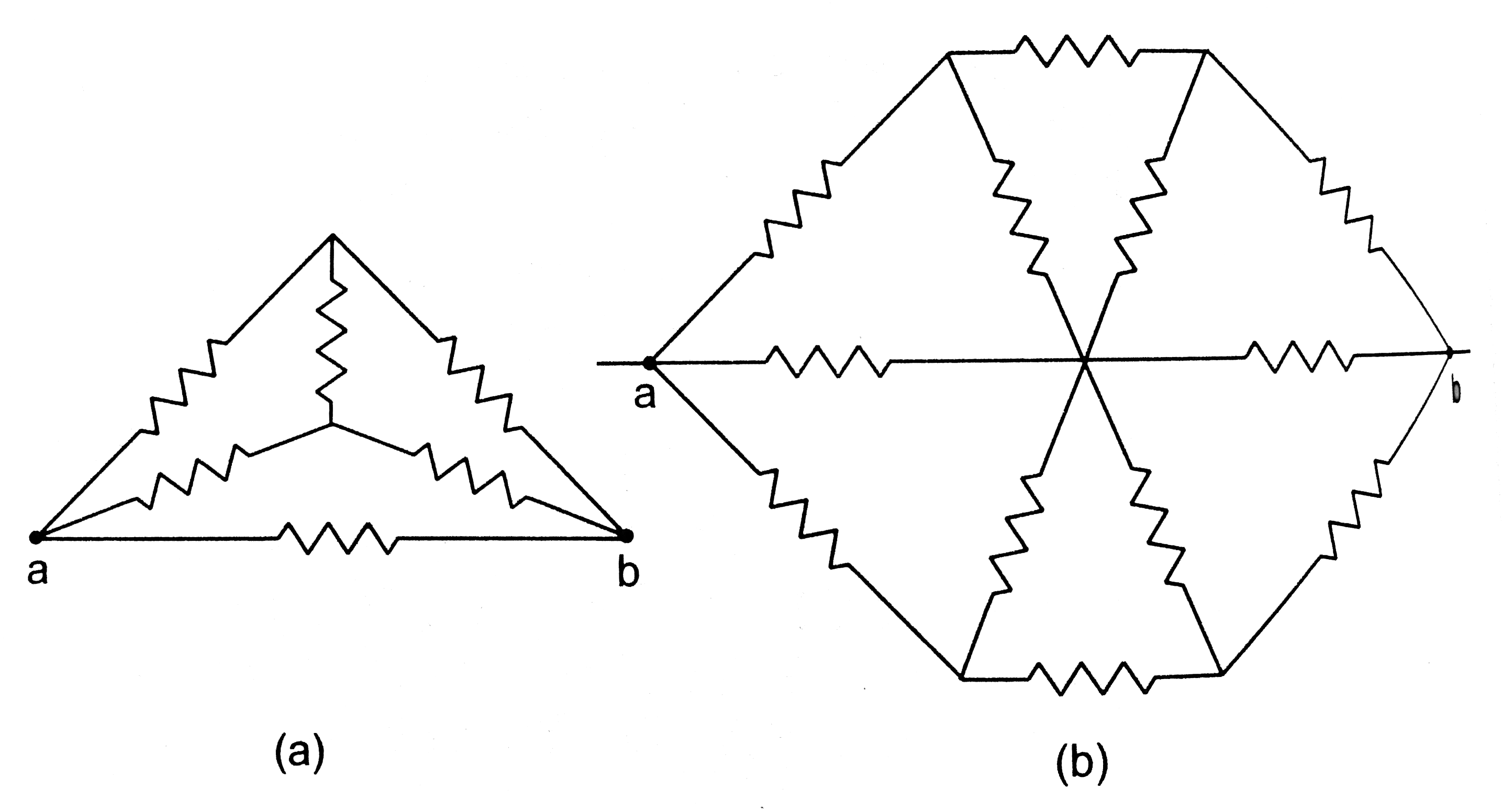
View SolutionFind the equivalent resistance of the circuits shown in figure between the points a and b. Each resistor has a resistance r.
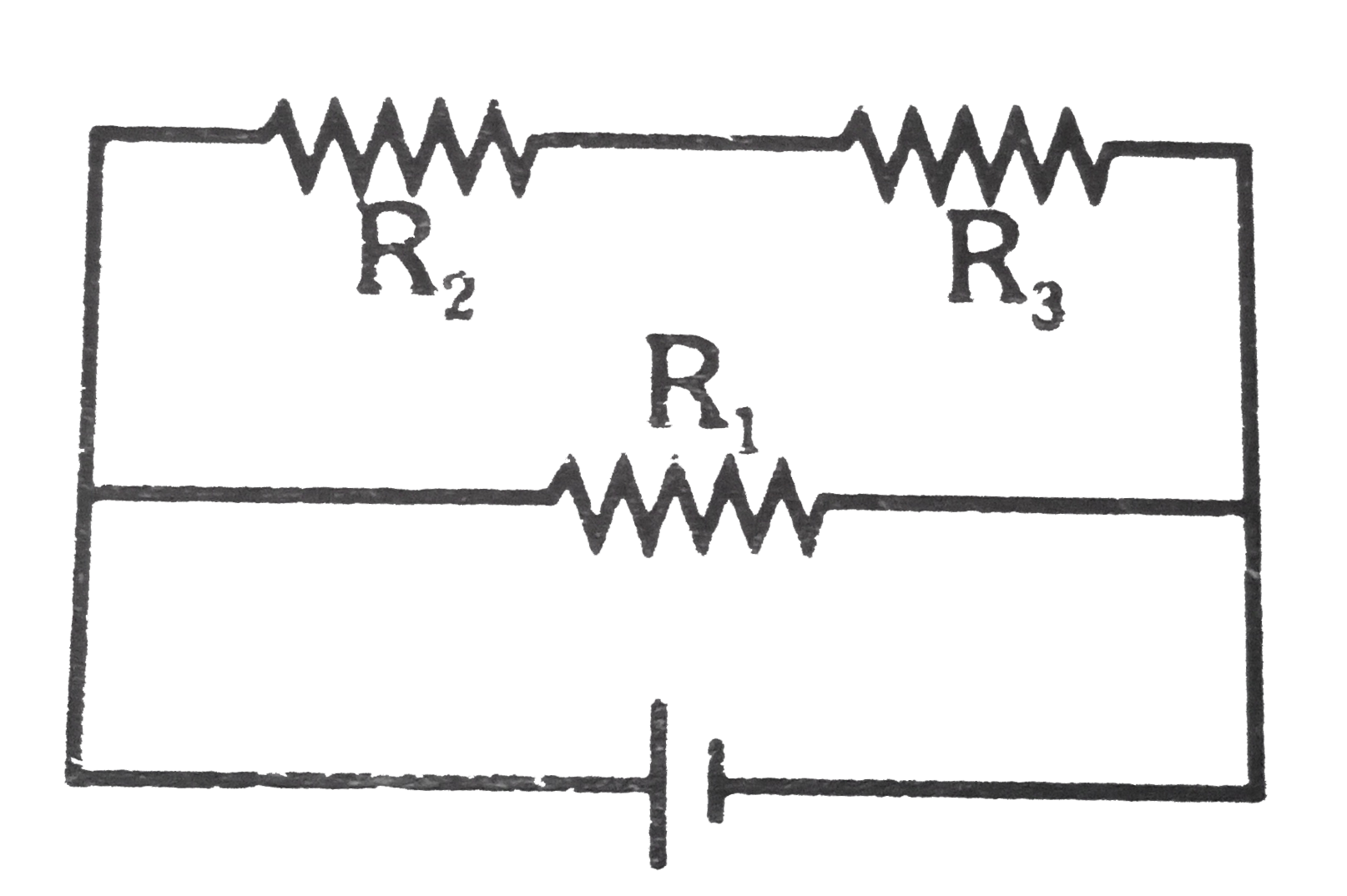
View SolutionIn given circuit R1=5Ω,R2=3Ω=7Ω and supply voltage is 10V. Calculate power dissipated in R1 and R3.
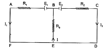
View SolutionIn the circuit shown below, E1=17V,E2=21V,R1=2Ω,R2=3ΩandR3=5Ω. Using Kirchhoff.s laws, find the currents flowing through the resistors R1,R2 and R3. (Internal resistance of each of the batteries is negligible.)
View Solution

