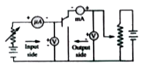
Draw a circuit diagram of transistor amplifier in CE configuration. Under what condition does the transistor acts as an amplifier?
Step-by-Step Solution:
1. Understanding the Circuit Configuration:
- The common emitter (CE) configuration is one of the most widely used transistor configurations for amplification. In this configuration, the emitter terminal is common to both the input and output circuits.
2. Drawing the Circuit Diagram:
- Start by drawing the N-P-N transistor symbol. Label the terminals: Collector (C), Base (B), and Emitter (E).
- Connect a resistor (R1) from the base (B) to a positive voltage source (VBB), which will forward bias the base-emitter junction.
- Connect another resistor (R2) from the collector (C) to a higher positive voltage source (VCC), which will reverse bias the collector-base junction.
- Connect the emitter (E) to the ground.
- Finally, connect the output across the collector and emitter.
The circuit diagram will look like this:
VC|R2|C||B|R1|VBB|E|GND
3. Conditions for Amplification:
- For the transistor to act as an amplifier, the following conditions must be met:
- The base-emitter (BE) junction must be forward biased. This means that the voltage at the base (VBB) should be greater than the emitter voltage (VE) by at least 0.7V for silicon transistors.
- The collector-base (CB) junction must be reverse biased. This means that the voltage at the collector (VCC) should be higher than the voltage at the base (VB).
4. Phase Relationship:
- In this configuration, the output signal (taken across the collector and emitter) is inverted with respect to the input signal (applied at the base). This means there is a phase difference of 180 degrees between the input and output signals.
Conclusion:
The N-P-N transistor in common emitter configuration acts as an amplifier when the base-emitter junction is forward biased and the collector-base junction is reverse biased.
---
- The common emitter (CE) configuration is one of the most widely used transistor configurations for amplification. In this configuration, the emitter terminal is common to both the input and output circuits.
- Start by drawing the N-P-N transistor symbol. Label the terminals: Collector (C), Base (B), and Emitter (E).
- Connect a resistor (R1) from the base (B) to a positive voltage source (VBB), which will forward bias the base-emitter junction.
- Connect another resistor (R2) from the collector (C) to a higher positive voltage source (VCC), which will reverse bias the collector-base junction.
- Connect the emitter (E) to the ground.
- Finally, connect the output across the collector and emitter.
- For the transistor to act as an amplifier, the following conditions must be met:
- The base-emitter (BE) junction must be forward biased. This means that the voltage at the base (VBB) should be greater than the emitter voltage (VE) by at least 0.7V for silicon transistors.
- The collector-base (CB) junction must be reverse biased. This means that the voltage at the collector (VCC) should be higher than the voltage at the base (VB).
- In this configuration, the output signal (taken across the collector and emitter) is inverted with respect to the input signal (applied at the base). This means there is a phase difference of 180 degrees between the input and output signals.
The N-P-N transistor in common emitter configuration acts as an amplifier when the base-emitter junction is forward biased and the collector-base junction is reverse biased.
Similar Questions
Knowledge Check
For a transistor amplifier, the voltage gain
Aremains constant for all frequenciesBis high high and low frequencies and constant in the middle frequency rangeCis low at high and low frequencies and constant at mid frequenciesDnone of these
When N-P-N transistor is used as an amplifier-
View SolutionAssertio Wavelength of charachteristic X-rays is given by
1λ∝(1n21−1n22)
in trasnition from n2→n1 . In the abvoe relation proportionality constant is series dependent. For different series (K-series, L-series, etc. ) value of this constant will be different.
Reason For L-series value of this constant is less than the value for K-series
View SolutionThe circuit diagram below shows n-p-n transistor in CE configuration. For this configuration, mark the correct statement(s).

View SolutionThe symbol of p-n-p transistor is
View SolutionDraw a circuit diagram of C.E. transistor amplifier. Briefly explain its working and write the expression for (i) current gain (ii) voltage gain of the amplifier.
View SolutionIn the following transistor amplifier circuit β=50.Vce→ of the transistor is
View SolutionDraw a labelled circuit diagram of n - p - n germanium transistor in common emitter configuration. Explain briefly, how this transistor is used as a voltage amplifier.
View Solution
