To study the dependence of potential difference (V) on current I across Resistor (R), Four circuit diagrams are prepared.
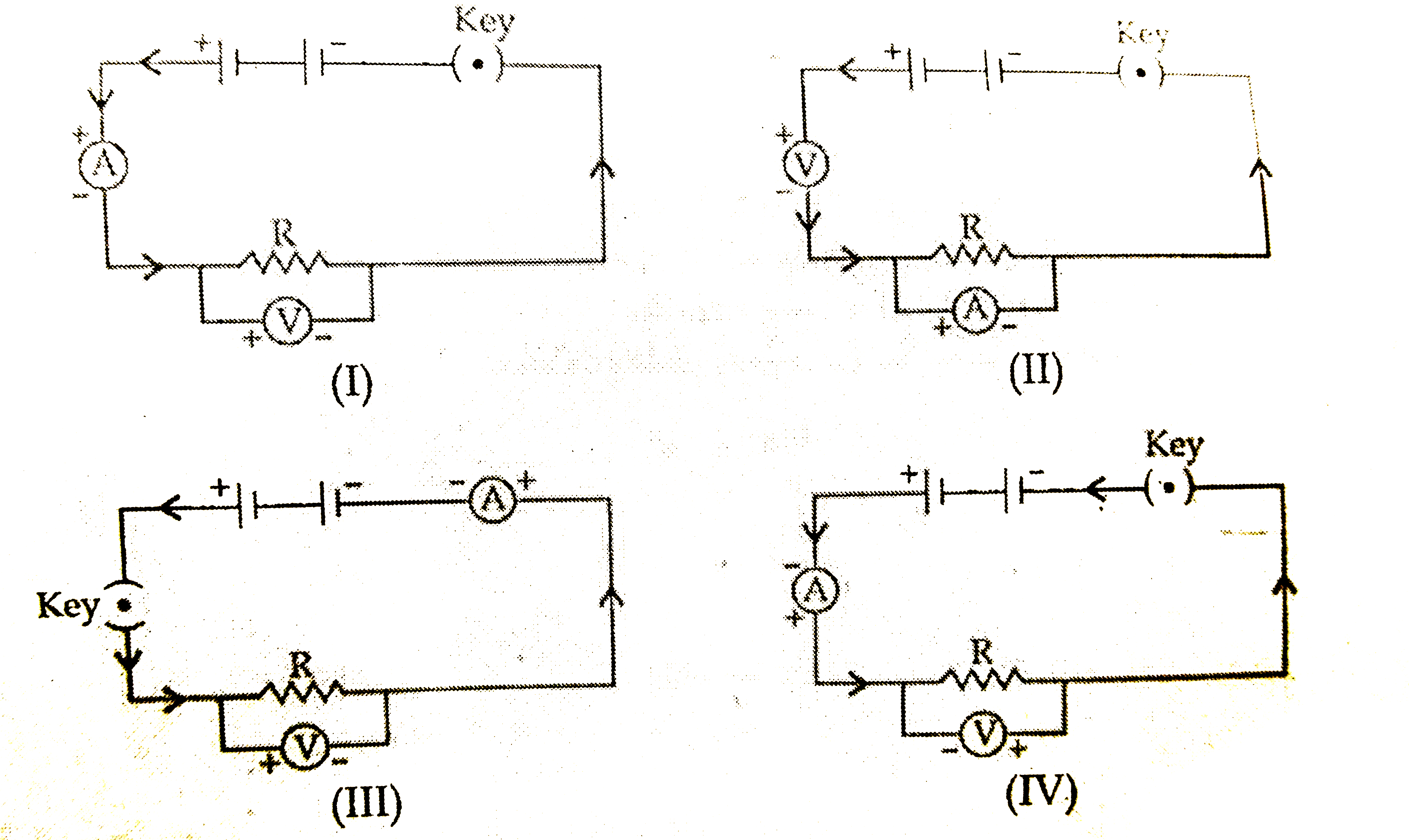
(i) Select the circuit diagrams which are correct.
(ii) Give reason for the circuit diagrams which are not correct.
Video Solution
Text Solution
(i) Circuit diagrams (I) and (III) are correct.
(ii) Circuit diagram (II) is incorrect because ammeter is always connected in series with resistor and voltmeter is always connected in parallel to the resistor.
Circuit diagram (IV) is incorrect because the negative (-ve) terminal of the ammeter and the voltmeter is connected to the positive (+ve) terminal of the battery and there is positive (+ve) terminals connection.
|
Updated on:21/07/2023
Similar Questions
Knowledge Check
- Question 1 - Select One
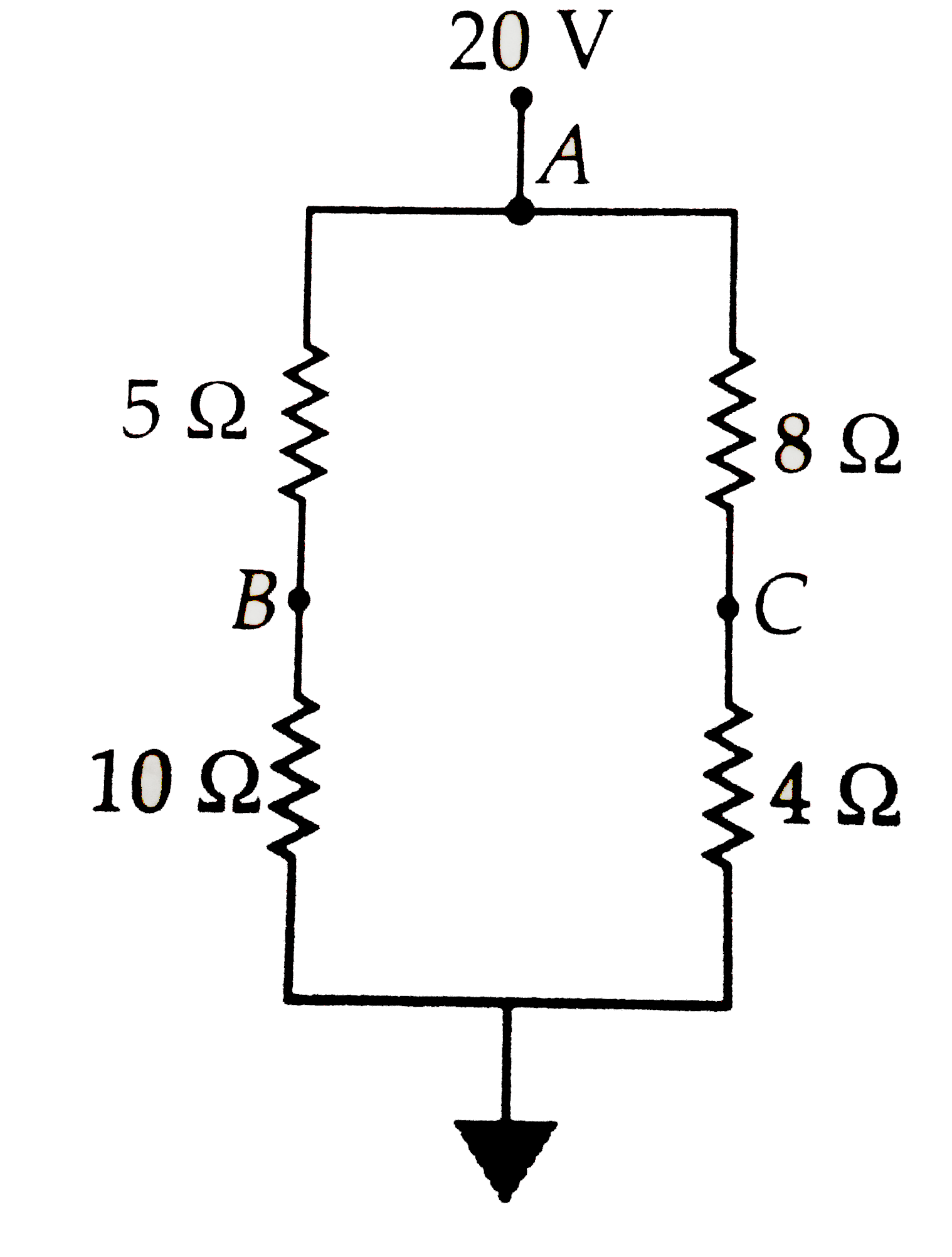
What is the potential difference between the points A and B in the circuit diagram shown in figure ?
 A203VB103VC20√3VD10√3V
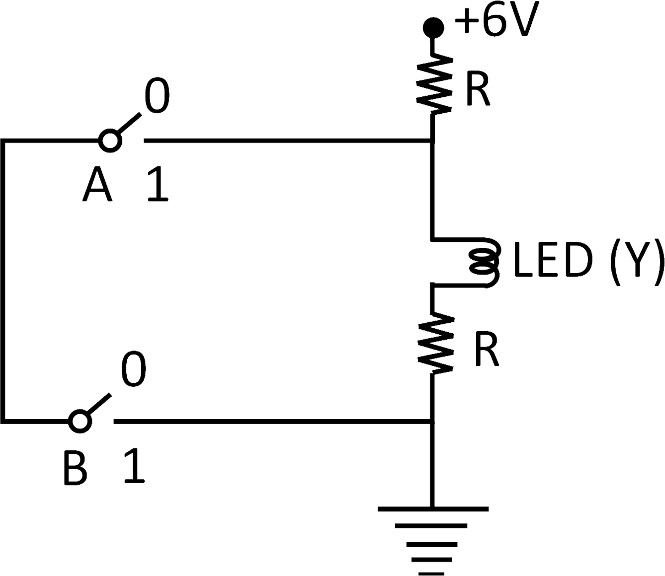
The correct Boolean operation represented by the circuit diagram drawn is
 View Solution
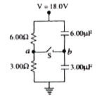
Study the following circuit diagram and mark the correct options.
 View Solution
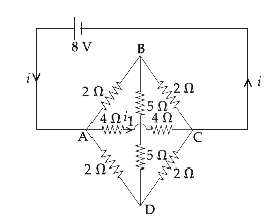
The value of current i1 flowing from A to C in the circuit diagram is :
 View Solution
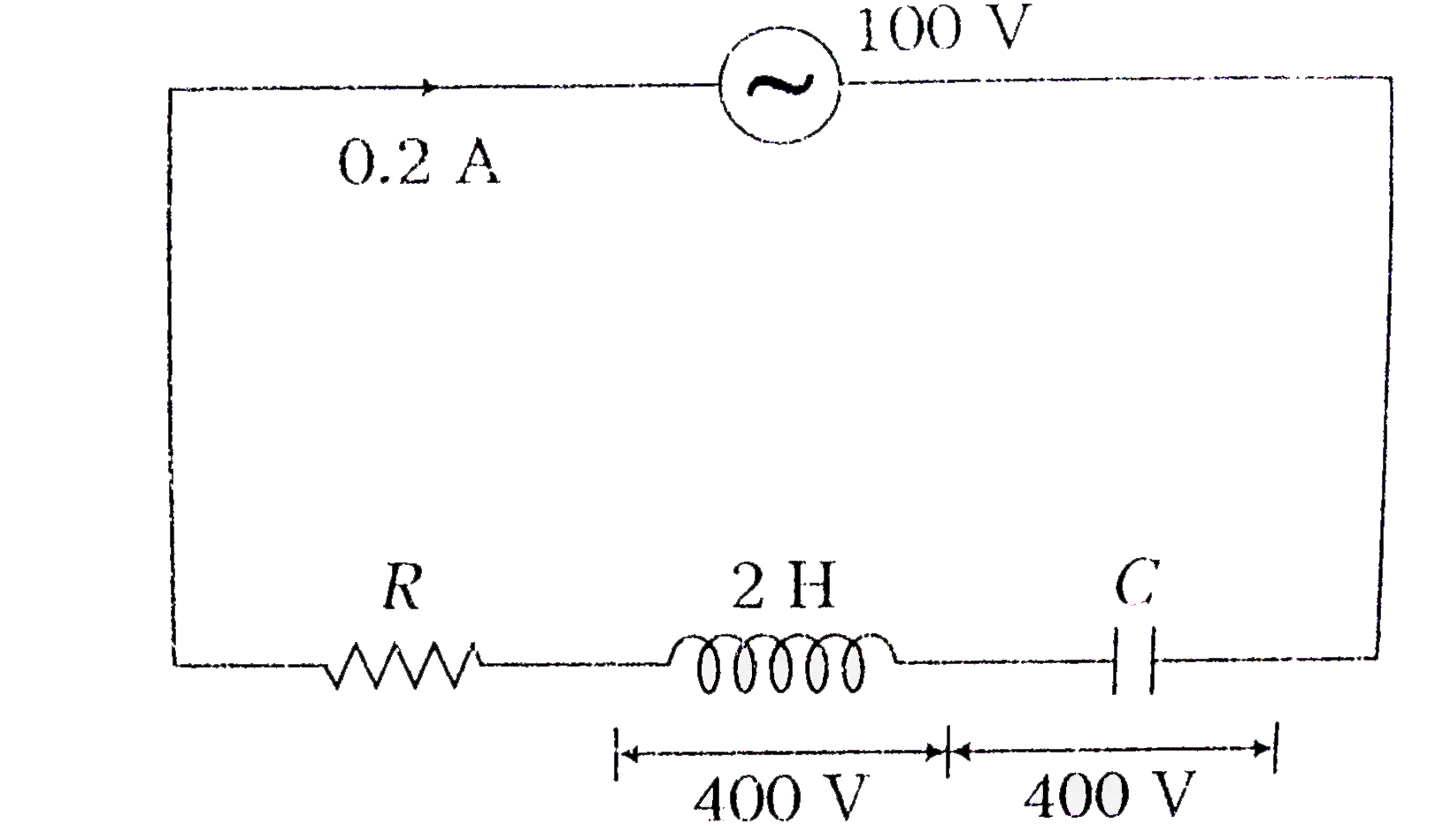
Which of the following options is correct with respect to the circuit diagram given below?
 View Solution
In the circuit diagram shown in find the current through the 1Ω resistor.
 View Solution
In the circuit shown, current in different branches are marked. Select the correct alternative(s)
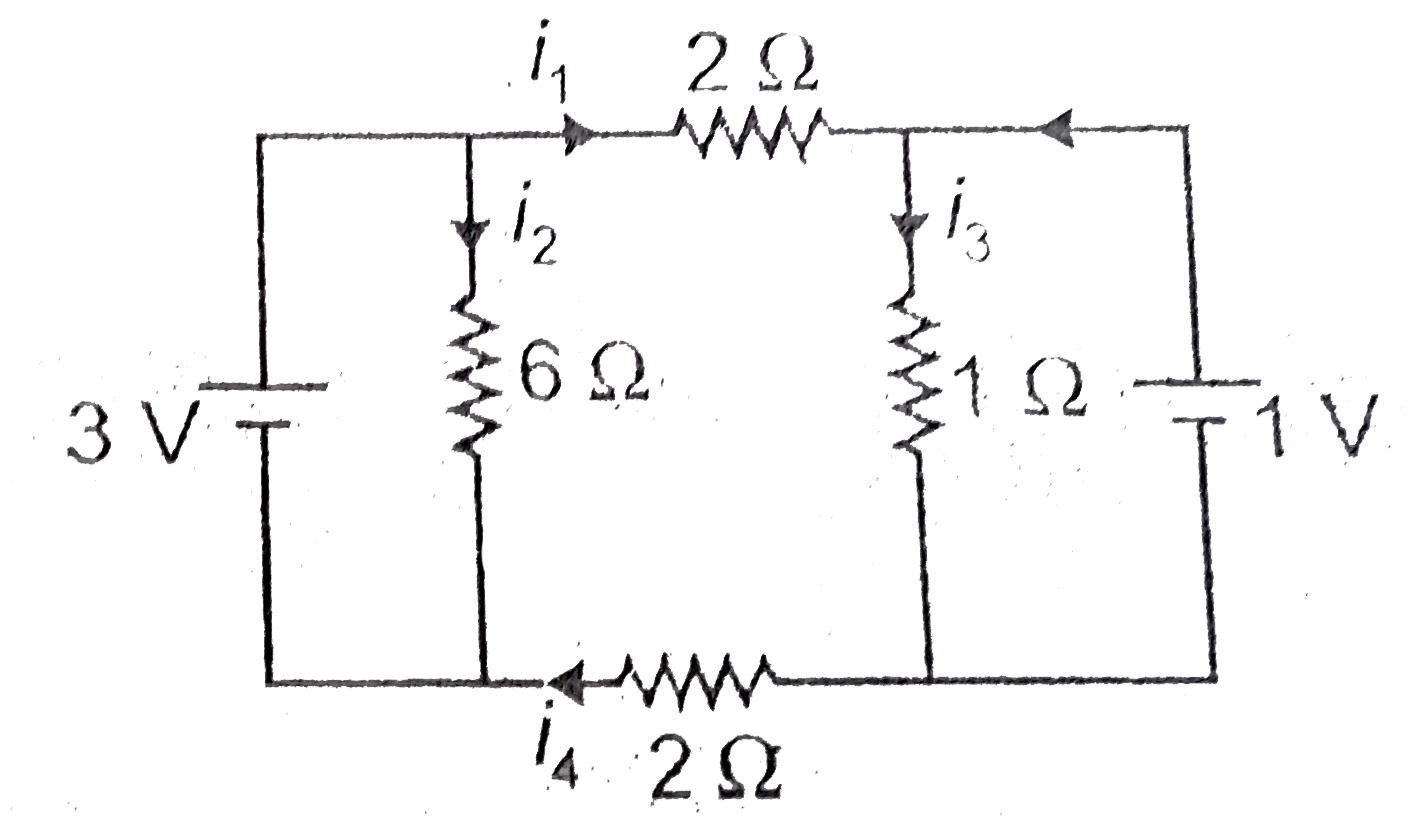 View Solution
Draw a labelled circuit diagram to study the dependence of current (I) on the potential
difference (V) across a resistor.View Solution


