An electrical system has open-closed switches S1,S2andS3 as shown in fig. The switches operate independently of one another and the current will flow from A→B either if S1 is closed or if both S2andS3 are closed. If P(S1)=P(S2)=P(S3)=1/2, then find the probability that the circuit will work. fig
To solve the problem, we need to find the probability that the electrical circuit will work given the conditions of the switches. Let's break this down step by step.
Step 1: Understand the conditions for the circuit to work
The circuit will work if:
1. Switch S1 is closed, or
2. Both switches S2 and S3 are closed.
Step 2: Define the events
Let:
- A be the event that switch S1 is closed.
- B be the event that both switches S2 and S3 are closed.
Step 3: Write the probability of the circuit working
The probability that the circuit works can be expressed as:
P(E)=P(A∪B)=P(A)+P(B)−P(A∩B)
Step 4: Calculate the individual probabilities
Given that:
P(S1)=P(S2)=P(S3)=12
We can calculate:
- P(A)=P(S1)=12
- P(B)=P(S2∩S3)=P(S2)⋅P(S3)=12⋅12=14
Step 5: Calculate the intersection probability
Since S1,S2, and S3 operate independently:
P(A∩B)=P(S1)⋅P(S2)⋅P(S3)=12⋅12⋅12=18
Step 6: Substitute values into the probability formula
Now substituting the values into the formula:
P(E)=P(A)+P(B)−P(A∩B)=12+14−18
Step 7: Find a common denominator and simplify
To simplify, we can convert all fractions to have a common denominator of 8:
P(E)=48+28−18=4+2−18=58
Conclusion
The probability that the circuit will work is:
58
---
The circuit will work if:
1. Switch S1 is closed, or
2. Both switches S2 and S3 are closed.
Let:
- A be the event that switch S1 is closed.
- B be the event that both switches S2 and S3 are closed.
The probability that the circuit works can be expressed as:
P(E)=P(A∪B)=P(A)+P(B)−P(A∩B)
Given that:
P(S1)=P(S2)=P(S3)=12
We can calculate:
- P(A)=P(S1)=12
- P(B)=P(S2∩S3)=P(S2)⋅P(S3)=12⋅12=14
Since S1,S2, and S3 operate independently:
P(A∩B)=P(S1)⋅P(S2)⋅P(S3)=12⋅12⋅12=18
Now substituting the values into the formula:
P(E)=P(A)+P(B)−P(A∩B)=12+14−18
To simplify, we can convert all fractions to have a common denominator of 8:
P(E)=48+28−18=4+2−18=58
The probability that the circuit will work is:
58
Topper's Solved these Questions
- BOOK - CENGAGE ENGLISHCHAPTER - PROBABILITY IIEXERCISE - SOLVED EXAMPLES21videos
PROBABILITY II
- BOOK - CENGAGE ENGLISHCHAPTER - PROBABILITY IIEXERCISE - CONCEPT APPCICATION EXERCISE 14.15videos
PROBABILITY II
- BOOK - CENGAGE ENGLISHCHAPTER - PROBABILITY I EXERCISE - JEE Advanced7videos
PROBABILITY I
- BOOK - CENGAGE ENGLISHCHAPTER - PROGRESSION AND SERIESEXERCISE - ARCHIVES (MATRIX MATCH TYPE )1videos
PROGRESSION AND SERIES
Similar Questions
An electrical system has open-closed switches S1,S2 and S3 as shown in fig. The switches operate independently of one another and the current will flow from A→B either if S1 is closed or if both S2 and S3 are closed. If P(S1)=P(S2)=P(S3)=1/2, then find the probability that the circuit will work.
View SolutionIn fig. A2.27, the charge that flows from P to Q when the switch S is closed is
 View Solution
Which of two switches S1andS2 shown in Fig. 7.31 will produce short - circuiting?
 View Solution
Consider the situation shown in figure. The switch S is open for a long time and then closed.

Find the charge flown through the battery when the switch S is closed.View SolutionWhen the switch S, in the circuit shown, is closed, then the value of current I will be :
 View Solution
If two switches S1andS2 have respectively 90% and 80% chances of working. Find the probabilities that each of eth following circuits will work.
View SolutionConsider the situation shown in figure (31-E23 ) . The switch S is open for a long time and then closed . (a) Find the charge flown through the battery when the switch S is closed (b)Find the work done by the battery .
 View Solution
As the switch S is closed in the circuit shown in figure, current passed through it is.
 View Solution
What is the probability that series circuit with three switches S1, S2and S3 with probabilities 13,12and34 respectively of functioning will work?
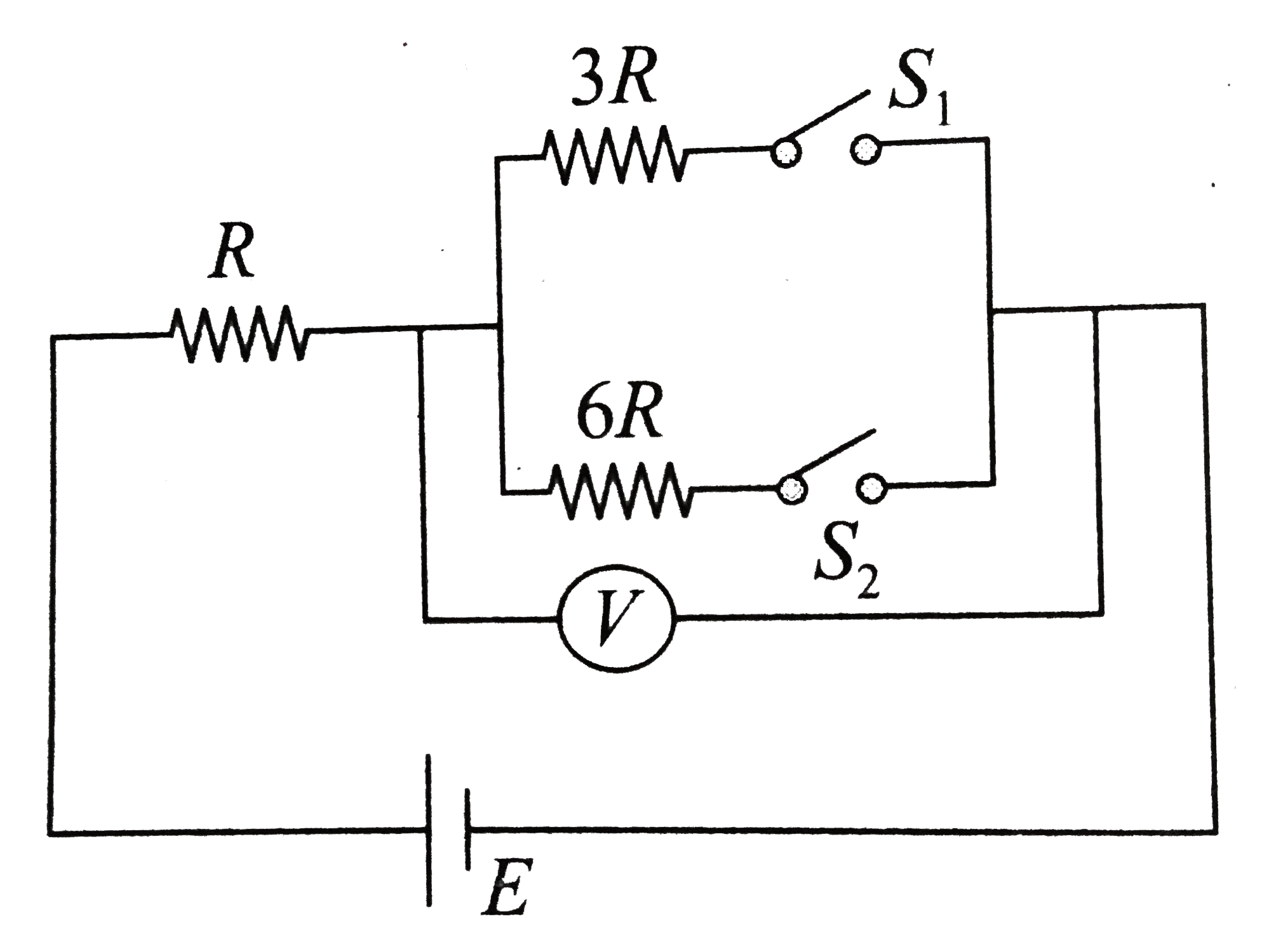
View SolutionIn the circuit shown in figure, reading of voltmeter is V1 when only S1 is closed, reading of voltmeter is V2 when only S2 is closed, and reading of voltmeter is V3 when both S1andS2 are closed. Then .
 View Solution

