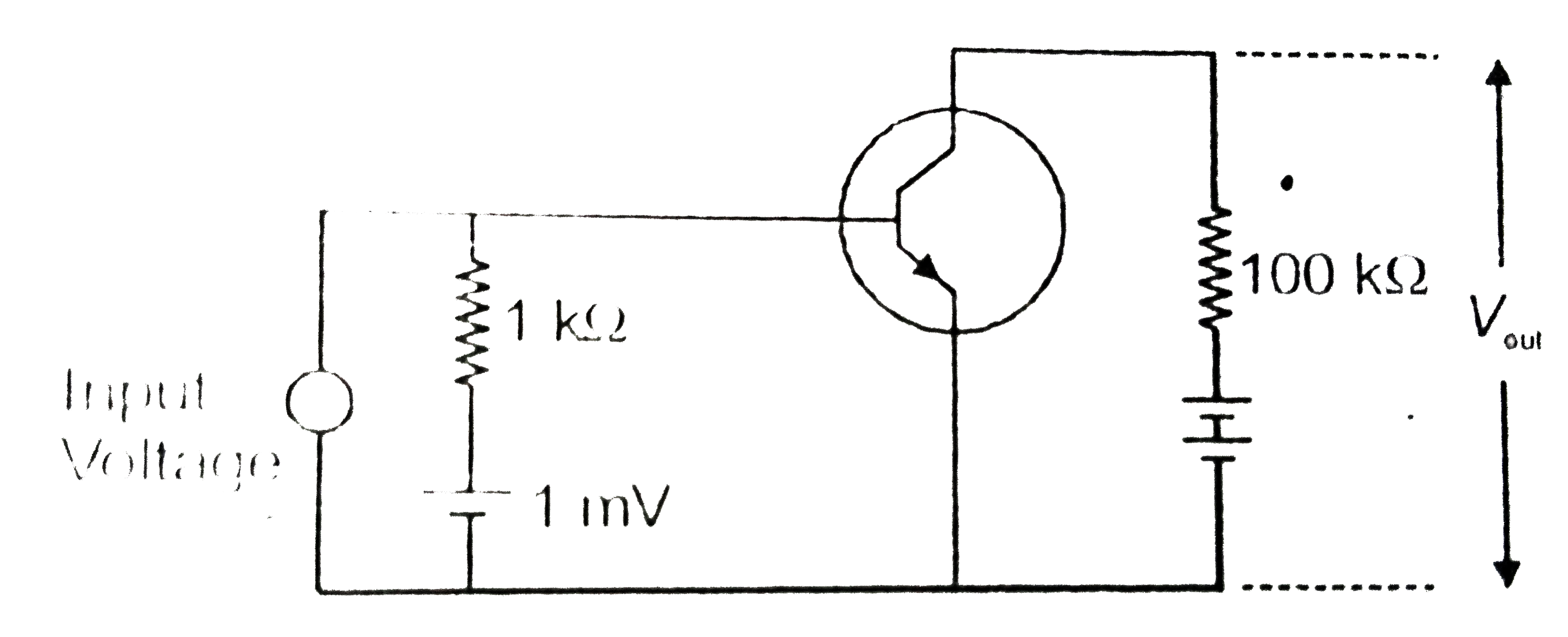
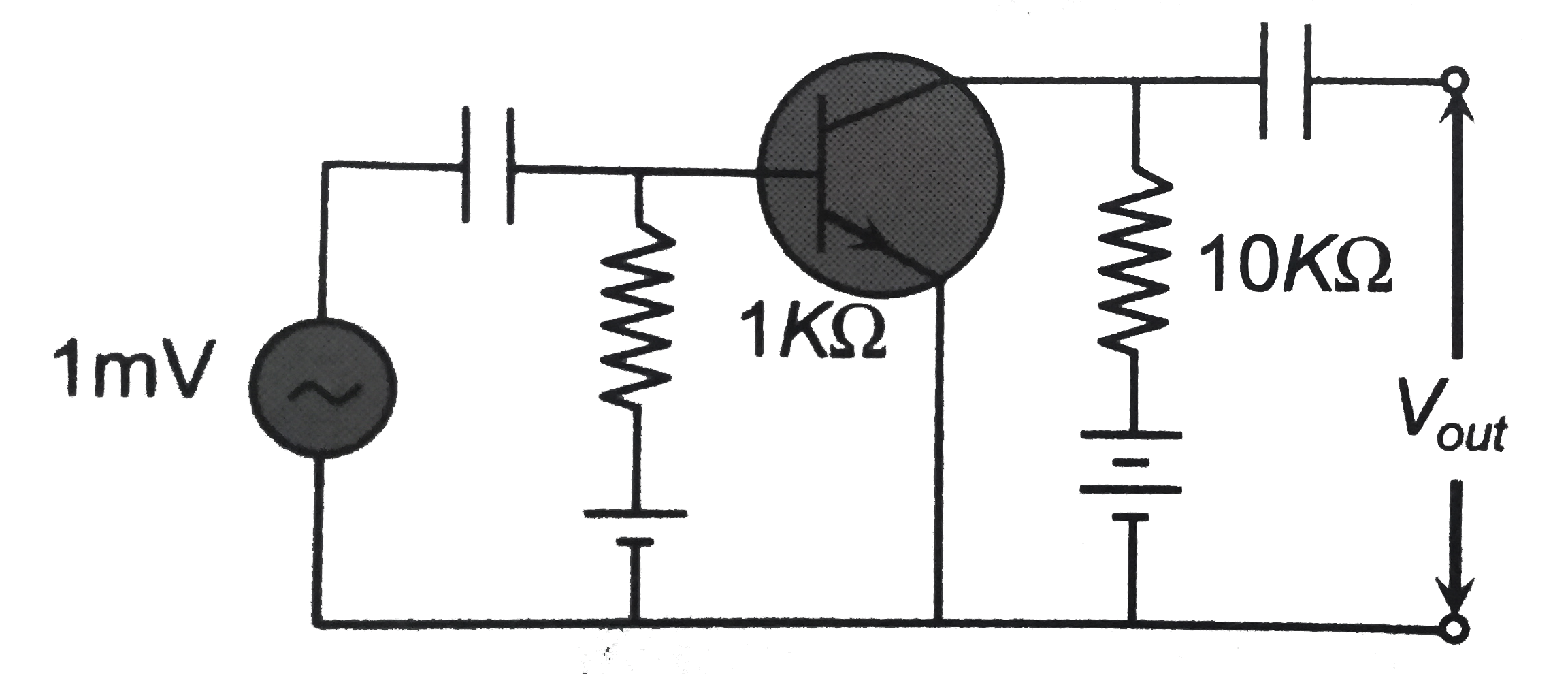
In a common emitter amplifier circuit using an n-p-n transistor, the phase difference between the input and the output voltages will be:-
Option1 180
Option2 45 degree
Option3 90 degree
Option4 135 degree
The correct Answer is:C
To determine the phase difference between the input and output voltages in a common emitter amplifier circuit using an NPN transistor, we can follow these steps:
1. Understanding the Common Emitter Configuration:
- In a common emitter amplifier, the input signal is applied between the base and the emitter, while the output is taken from the collector with respect to the emitter.
2. Signal Inversion:
- The common emitter configuration is known for its ability to invert the input signal. This means that when the input voltage increases, the output voltage decreases, and vice versa.
3. Phase Relationship:
- Since the output voltage is inverted relative to the input voltage, there is a phase shift of 180 degrees. This can be visualized as follows:
- If the input waveform is a sine wave, the output waveform will be a sine wave that is flipped upside down.
4. Conclusion:
- Therefore, the phase difference between the input and output voltages in a common emitter amplifier circuit using an NPN transistor is 180 degrees.
Final Answer:
The phase difference between the input and the output voltages will be 180 degrees.
---
- In a common emitter amplifier, the input signal is applied between the base and the emitter, while the output is taken from the collector with respect to the emitter.
- The common emitter configuration is known for its ability to invert the input signal. This means that when the input voltage increases, the output voltage decreases, and vice versa.
- Since the output voltage is inverted relative to the input voltage, there is a phase shift of 180 degrees. This can be visualized as follows:
- If the input waveform is a sine wave, the output waveform will be a sine wave that is flipped upside down.
- Therefore, the phase difference between the input and output voltages in a common emitter amplifier circuit using an NPN transistor is 180 degrees.
The phase difference between the input and the output voltages will be 180 degrees.
Topper's Solved these Questions
Similar Questions
Knowledge Check
A transistor has a current amplification factor (current gain) of 50. In a common emitter amplifier circuit, the collector resistance is chosen as 5Ω and the input resistance is 1Ω. The output voltage if input voltage is 0.01 V is
A-2 VB−5VC-2.5 VD-1 V
When a triode is used as an amplifier the phase difference between the input signal voltage and the output is
View SolutionIn a common emitter amplifier, the input and output voltage are out of phase by
View SolutionGive a circuit diagram of a common emitter amplifier using an n-p-n transistor. Draw the input and output wavefroms of the signal. Write the expression for its voltage gain.
View SolutionIn the following common emitter configuration an n-p-n transistor with current gain β=100 is used. What is the output voltage of the amplifier ?

View SolutionIn the following common emitter configuration an NPN transistor with current gain β=100 is used. The output voltage of the amlifier will be

View SolutionIn the following common emitter configuration an NPN transistor with current gain β=100 is used. The output voltage of the amlifier will be

View SolutionA common-emitter amplifier is designed with an n-p-n transistor (α=0.99).The input impedance is 1kΩand the load is 10kΩ.The voltage gain will be
View Solution
