A student was trying to constant the circuit shown in the figure below marked (a), but ended up constructing the circuit marked (b). Realizing her mistake, she corrected the circuit, but the her surpris, the output voltage (across R) did not change

100Ω
150Ω
200Ω
300Ω
Step by step video & image solution for A student was trying to constant the circuit shown in the figure below marked (a), but ended up constructing the circuit marked (b). Realizing her mistake, she corrected the circuit, but the her surpris, the output voltage (across R) did not change by Physics experts to help you in doubts & scoring excellent marks in Class 12 exams.
Topper's Solved these Questions
- BOOK - KVPY PREVIOUS YEARCHAPTER - KVPY 2021EXERCISE - PART-I Physics13videos
KVPY 2021
- BOOK - KVPY PREVIOUS YEARCHAPTER - KVPY 2021EXERCISE - PART II PHYSICS9videos
KVPY 2021
- BOOK - KVPY PREVIOUS YEARCHAPTER - KVPYEXERCISE - All Questions415videos
KVPY
- BOOK - KVPY PREVIOUS YEARCHAPTER - MOCK TEST 1EXERCISE - EXERCISE23videos
MOCK TEST 1
Similar Questions
Find the equivalent resistance of the circuit shown in figure-3.64 across terminals A and B. Each resistance in this circuit is of resistance R.
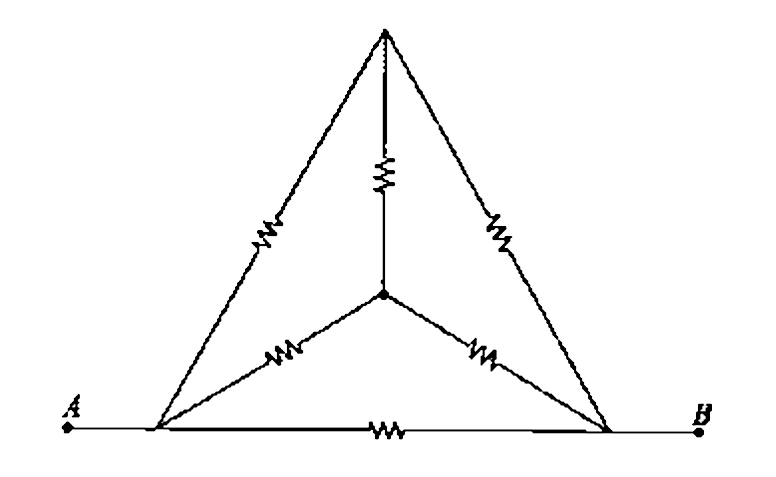 View Solution
For the circuit shown in figure, Find
(1) the output voltage ,
(2) the voltage drop across series resistance ,
(3) the current through Zener diode.
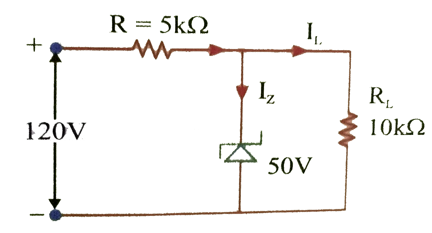 .View Solution
Knowledge Check
- Question 1 - Select One
A student was trying to construct the circuit shown in the figure below maked (a), but ended up constructing the circuit marked (b). Realizing her mistake, she corrected the circuit , but to her surprise, the output voltage (across R) did not change.
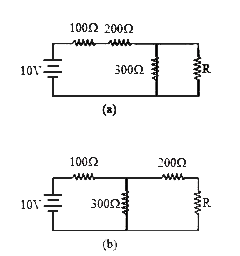
The value of resistance R is :-A100 ΩB150ΩC200ΩD300Ω - Question 2 - Select One
For the circuit shown in the figure the rms value of voltage across R and coil are E1 and E2 respectively.
The power (thermal) developed across the coil is
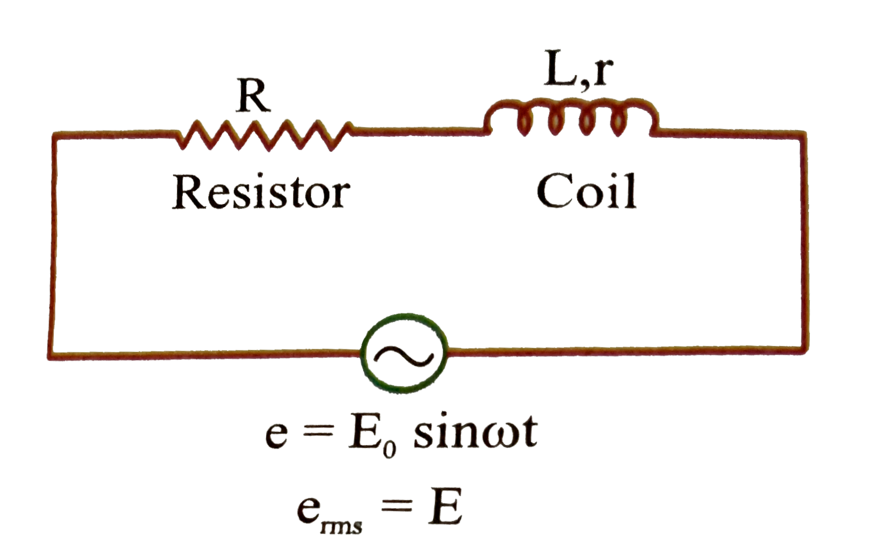 AE−E212RBE−E21−E222RCE22RD(E−E1)22R
 - Question 3 - Select One
Thirteen resistances each of resistance R ohm are connected in the circuit as shown in the figure below. The effecitve resistance between A and B is
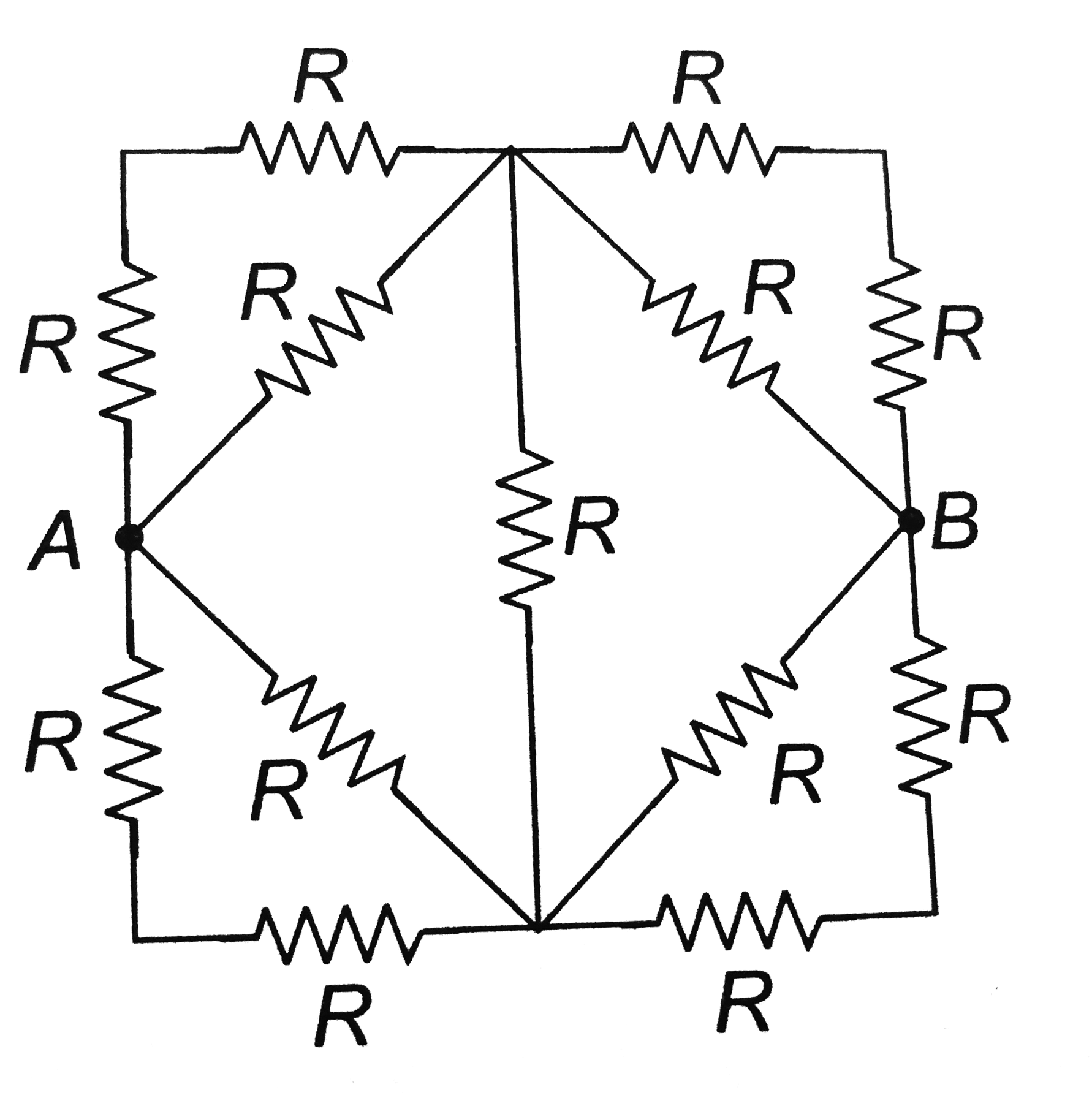 A2RΩB4R3ΩC2R3DRΩ
In the circuit shown in the figure , the resistance marked R can be varied by using a Rheostat. The power across the 5 Omega resistor will be maximum if the Rhoestat has resistance equal to
_PHY_E01_015_Q01.png) View Solution
View SolutionFrom the zener diode circuit shown in the figure, find (1) the output voltage (2) the voltage drop across series resistance and (3) the current through zener diode.
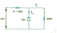 View Solution
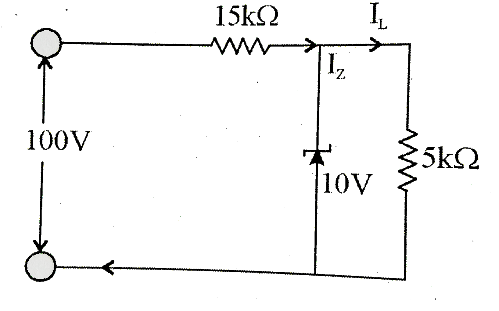
for the circuit shown in figure, find
(i). The output voltage
(ii). The votlage drop across series resistance
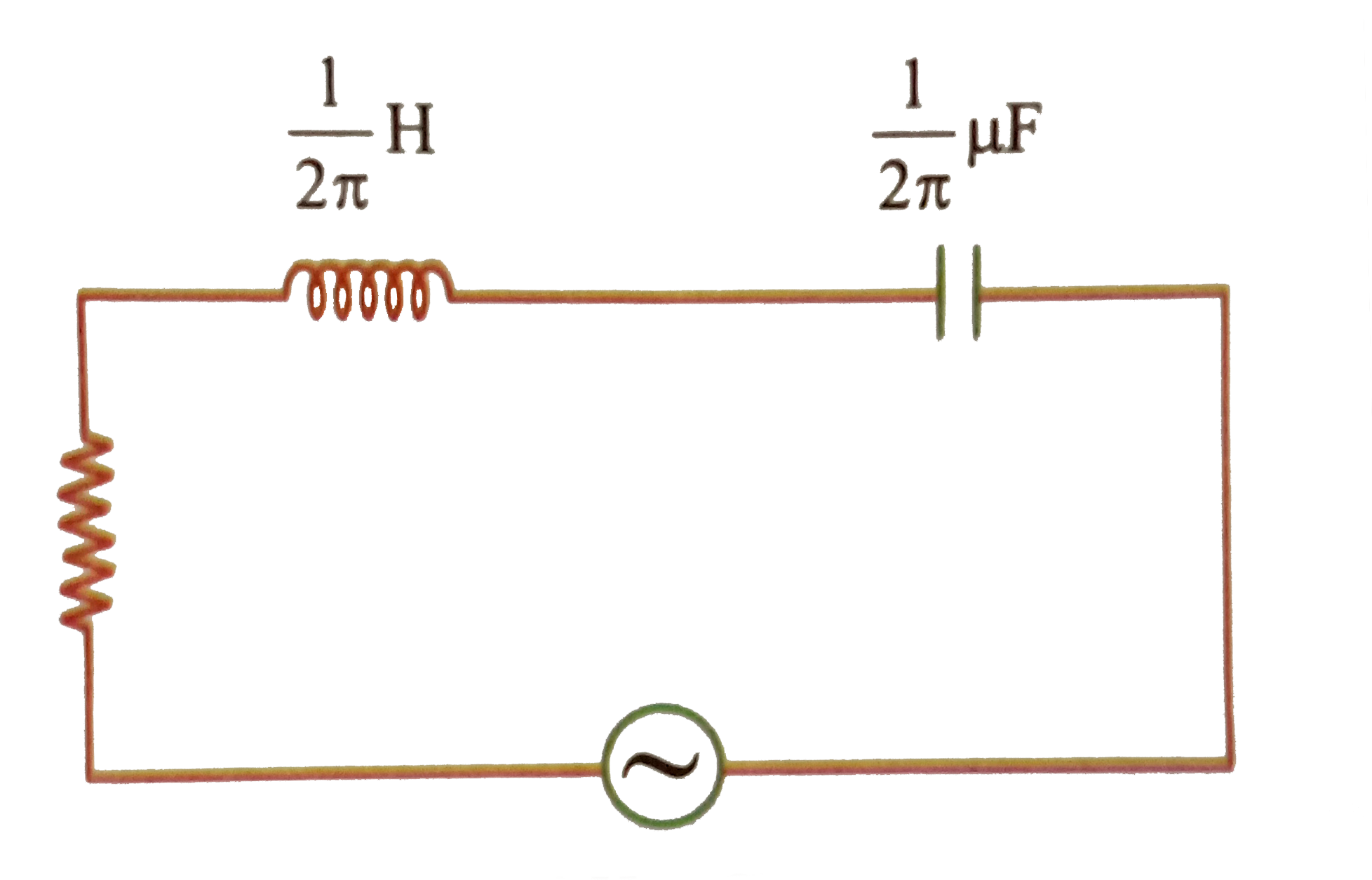
(iii). The current through zener diode.View SolutionIn the a.c. circuit shown in the figure. The supply voltage has a constant r.m.s value V but varialbe frequency f. Resonance frequency in hertz is
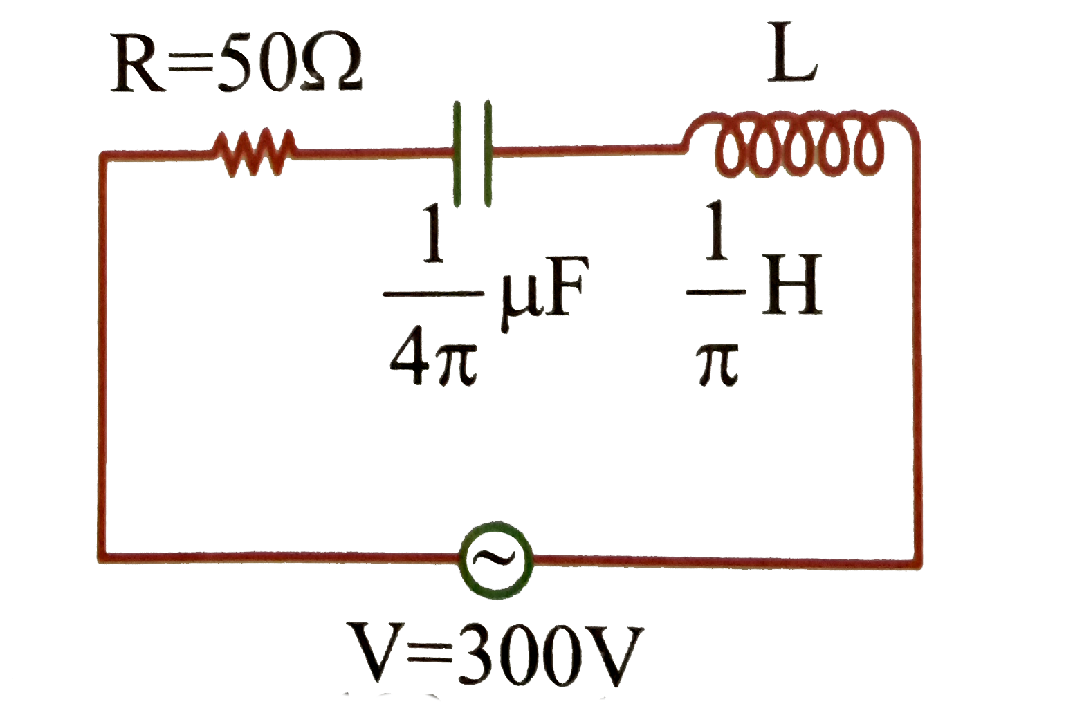 View Solution
In the a.c circuit shown in figure, the supply voltage has a constant r.m.s value but variable frquency f. Resonance frequency is
 View Solution

