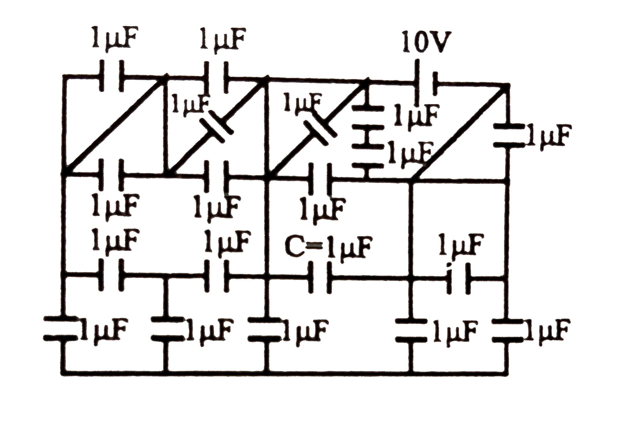
Find the change on the capacity C=1μF in the circuit shown in the figure .
10μC
13μC
12μC
24μC
The correct Answer is:A
Topper's Solved these Questions
- CAPACITORS BOOK - AAKASH SERIESCHAPTER - CAPACITORS EXERCISE - LECTURE SHEET (EXERCISE - I) (LEVEL - II (ADVANCED)) (Matrix Matching Type Questions)
2 Videos
- CAPACITORS BOOK - AAKASH SERIESCHAPTER - CAPACITORS EXERCISE - LECTURE SHEET (EXERCISE - I) (LEVEL - II (ADVANCED)) (Integer Type Questions)
1 Videos
- CAPACITORS BOOK - AAKASH SERIESCHAPTER - CAPACITORS EXERCISE - PRACTICE SHEET (ADVANCED) (Integer Type Questions)
2 Videos
- ATOMSBOOK - AAKASH SERIESCHAPTER - ATOMSEXERCISE - PRACTICE EXERCISE
21 Videos
- COMMUNICATION SYSTEM BOOK - AAKASH SERIESCHAPTER - COMMUNICATION SYSTEM EXERCISE - LECTURE SHEET (LEVEL - I) (MAIN) (EXERCISE - IV) (Straight Objective & More than one Correct Answer Type Questions)
20 Videos
Similar Questions
Knowledge Check
A capacitor of capacity C1=1μF is charged to a potential of 100 V. The charging battery is then removed and it is connected to another capacitor of capacity C2=2μF. One plate of C2 is earthed as shown in figure. The charges on C1andC2 in steady state will be
 A50μC,50μCB100μC,zeroC1003μC,2003μCDzero,zer
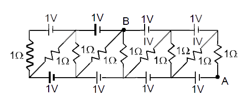
Find the potential difference VA−CB for the circuit shown in the figure .
View SolutionIn the circuit shown in figure , find the value of RC.
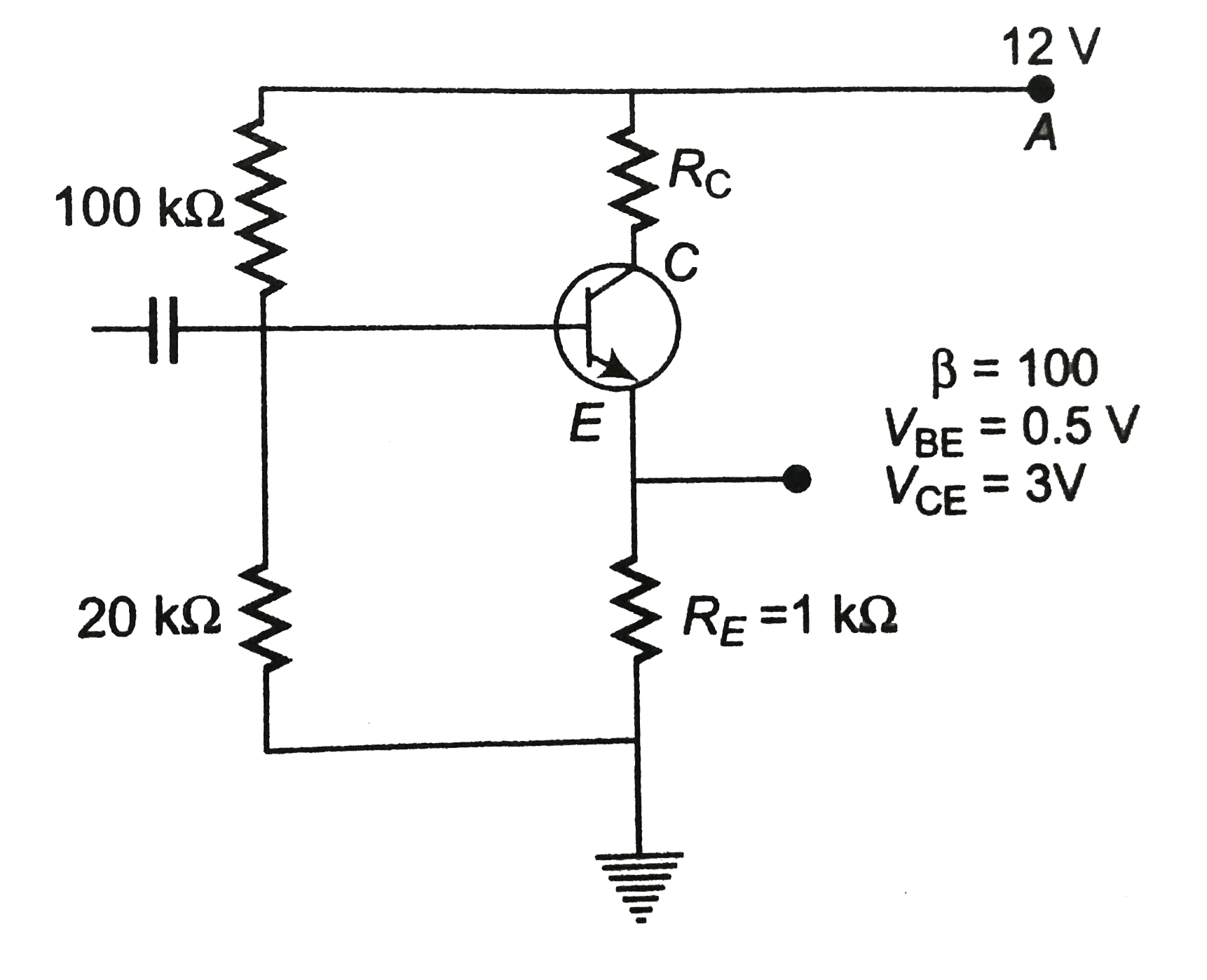
View Solution4 capacitors each of capacity 2μF are joined as shown in the figure. What is the capacity between the points A and B.
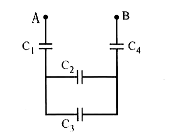
View SolutionFive capacitors each of capacity C are joined as shown in the following figure. If theire resultant capacity CR=2μF, then the capacity of each capacitor is
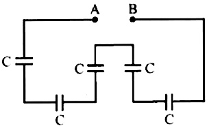
View SolutionA capacitor of capacity C1=1μF is charged to a potential of 100 V. The charging battery is then removed and it is connected to another capacitor of capacity C2=2μF. One plate of C2 is earthed as shown in figure. The charges on C1andC2 in steady state will be

View SolutionThree capacitors C1,C2,andC3 of capacitance 1μF,2μF,and3μF, respectively, are charged separately as shown in the figure. Now these charged capacitors are connected to a battery of ε=20V and an uncharged capacitor of C=2μF as shown in figure.
 ,
, 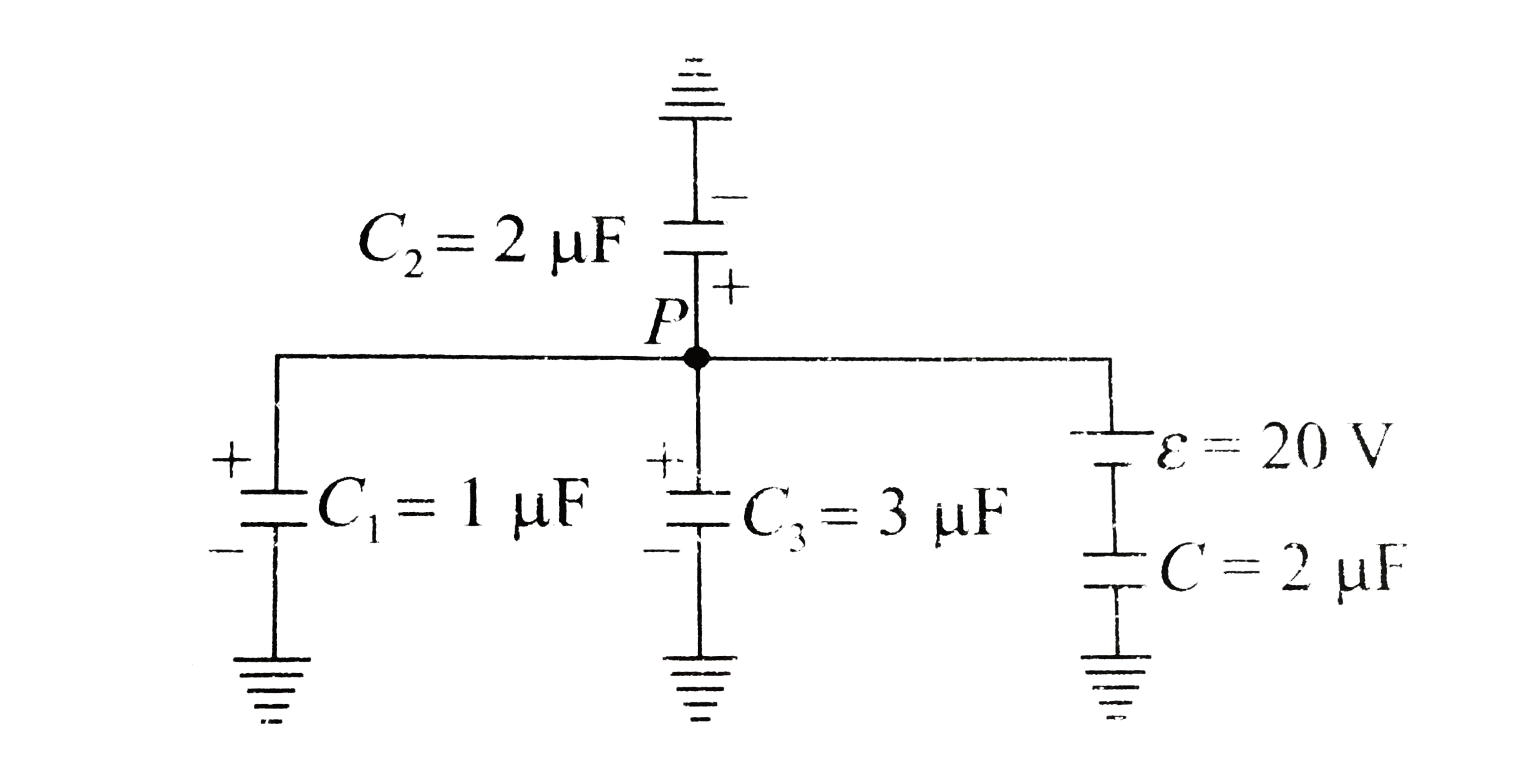
The charge on capacitor marked C is
View SolutionThree capacitors C1,C2,andC3 of capacitance 1μF,2μF,and3μF, respectively, are charged separately as shown in the figure. Now these charged capacitors are connected to a battery of ε=20V and an uncharged capacitor of C=2μF as shown in figure.
 ,
, 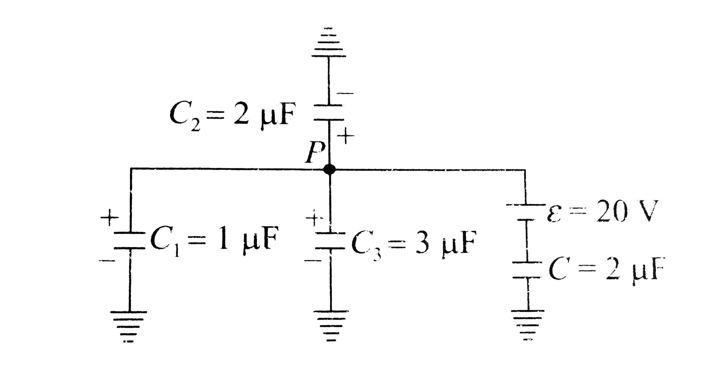
The potential of point P is
View Solution

