The figure shows a diagonal symetric arrangement of capacitors and a battery.
The value of charge q1,q2andq3 as shown in the figure are

q1=32μC,q2=24μC,q3=−8μC
q1=48μC,q2=16μC,q3=+8μC
q1=32μC,q2=24μC,q3=+8μC
q1=3μC,q2=4μC,q3=+2μC
The correct Answer is:C
Topper's Solved these Questions
- CAPACITORS BOOK - AAKASH SERIESCHAPTER - CAPACITORS EXERCISE - LECTURE SHEET (EXERCISE - II) (LEVEL - I (ADVANCED)) (Integer Type Questions )
1 Video
- CAPACITORS BOOK - AAKASH SERIESCHAPTER - CAPACITORS EXERCISE - LECTURE SHEET (EXERCISE - III) (LEVEL - I (MAIN)) (Straight Objective Type Questions )
3 Videos
- CAPACITORS BOOK - AAKASH SERIESCHAPTER - CAPACITORS EXERCISE - LECTURE SHEET (EXERCISE - II) (LEVEL - I (ADVANCED)) (More than one correct answer Type Questions )
2 Videos
- ATOMSBOOK - AAKASH SERIESCHAPTER - ATOMSEXERCISE - PRACTICE EXERCISE
21 Videos
- COMMUNICATION SYSTEM BOOK - AAKASH SERIESCHAPTER - COMMUNICATION SYSTEM EXERCISE - LECTURE SHEET (LEVEL - I) (MAIN) (EXERCISE - IV) (Straight Objective & More than one Correct Answer Type Questions)
20 Videos
Similar Questions
The figure shows a diagonal symetric arrangement of capacitors and a battery.
Identify the correct statements

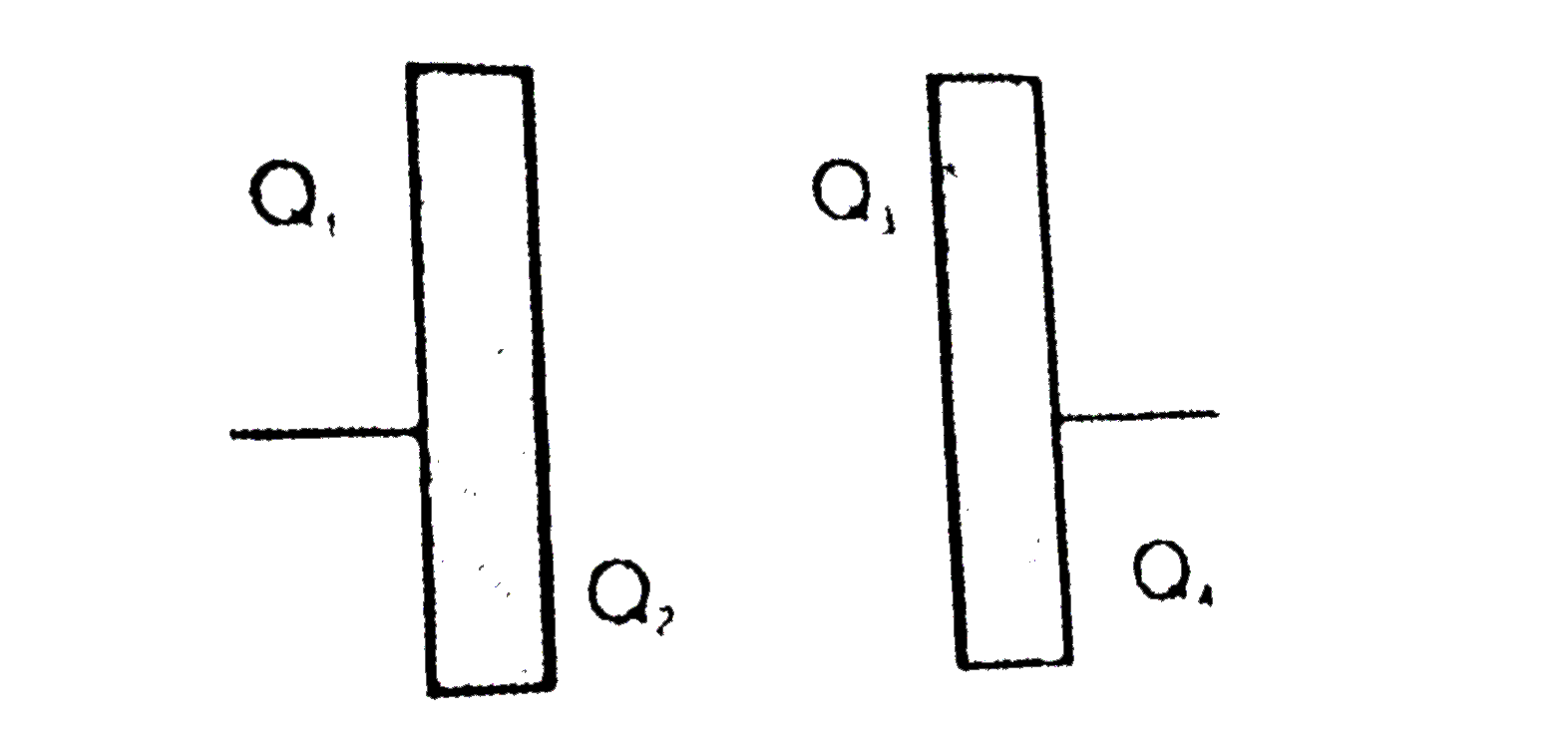
View SolutionIn an isolated parallel plate capacitor of capacitance C the four surfaces have charges Q1,Q2,Q3 and Q4 as shown in the figure. The potential difference between the plates is :

View Solution
Knowledge Check
In an isolated parallel plate capacitor of capacitance C the four surfaces have charges Q1,Q2,Q3 and Q4 as shown in the figure. The potential difference between the plates is :
 AQ1+Q2CB∣∣∣Q2C∣∣∣C∣∣∣Q3C∣∣∣D1C[(Q1+Q2)−(Q3−Q4)]
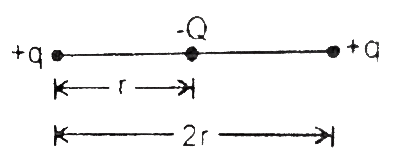
Figure shown an arrangement of three points charges. The total potential energy of this arrangement zero. The ratio qQ is :
 A4:1B2:1C1:1D1:2
The figure shown is a plot of electric field lines due to two charges Q1 and Q2 . The sign of charges is

View SolutionThe figure-3.375 shows two circuits with a charged capacitor that is to be discharged through a resistor as shown in the figure. The ratio of initial charges on capacitors is given as q2/q1=2. If both switches are closed at time t=0, the charges become equal at 10−4ln2s. Find the resistance R.

View SolutionA charge Q is placed at the centre of the line joining two point charges +q and +q as shown in figure. The ratio of charges Q and q is

View SolutionA charge Q is placed at the centre of the line joining two point charges +q and +q as shown in figure. The ratio of charges Q and q is

View SolutionFind the electric charge Q1 on plates of capacitor C_(1), shown in figure below :
View Solution
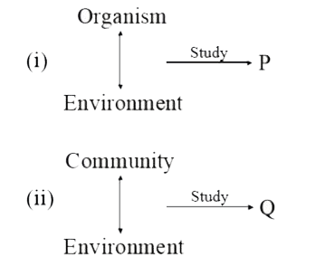
then P and Q are respectively called as.
View Solution
