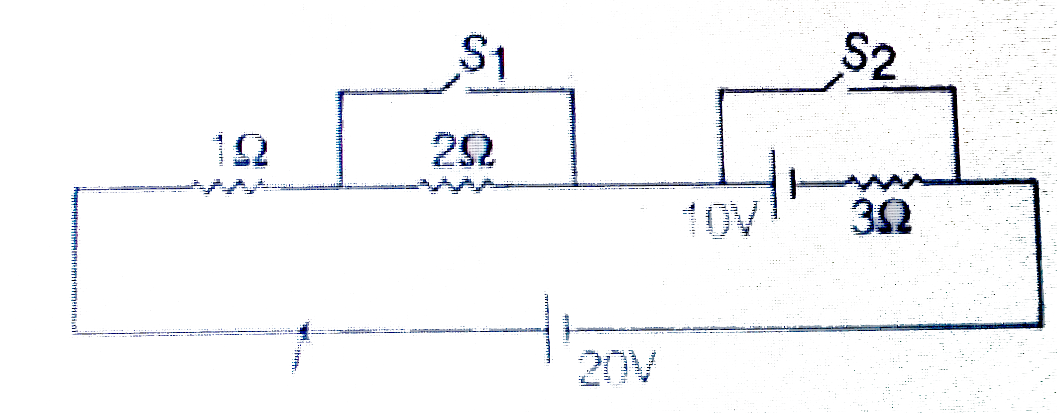
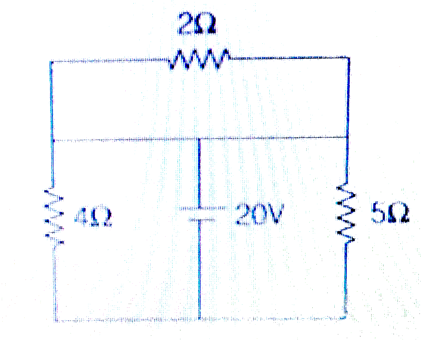
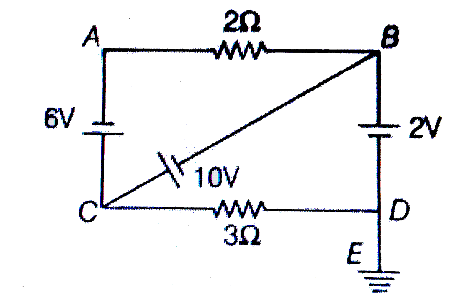
In the diode circuit shown in figure,

A
D1andD2 are reverse biased
B
D1andD2 are forward biased
C
D1 is forward biased and D2 is reverse biased.
D
D1 is reverse biased and D2 is forward biased.
Video Solution
Text Solution
The correct Answer is:C
|
Answer
Step by step video & text solution for In the diode circuit shown in figure, by Physics experts to help you in doubts & scoring excellent marks in Class 12 exams.
Updated on:21/07/2023
Topper's Solved these Questions
- BOOK - MTG GUIDECHAPTER - ELECTRONIC DEVICESEXERCISE - CHECK YOUR BEET VITALS25videos
ELECTRONIC DEVICES
- BOOK - MTG GUIDECHAPTER - ELECTRONIC DEVICESEXERCISE - AIPMT/NEET (MCQs)42videos
ELECTRONIC DEVICES
- BOOK - MTG GUIDECHAPTER - ELECTRONIC DEVICESEXERCISE - AIPMT/NEET (MCQs)42videos
ELECTRONIC DEVICES
- BOOK - MTG GUIDECHAPTER - ELECTROMAGNETIC WAVESEXERCISE - AIPMT/NEET(MCQs)15videos
ELECTROMAGNETIC WAVES
- BOOK - MTG GUIDECHAPTER - ELECTROSTATICSEXERCISE - AIPMT/NEET (MCQ.s)34videos
ELECTROSTATICS
Similar Questions
Knowledge Check
- Question 1 - Select One
From the Zener diode circuit shown in figure, the current through the Zener diode is
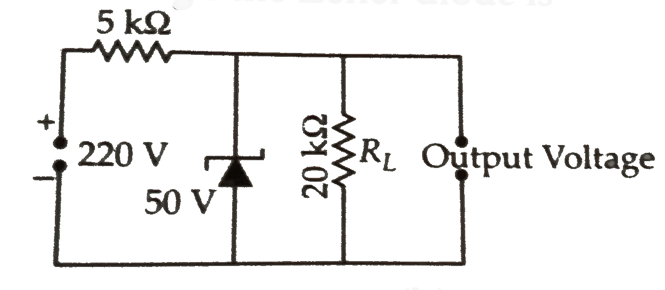 A34 mAB31.5 mAC36.5 mAD2.5 mA
 - Question 2 - Select One
From the Zener diode circuit shown in figure, the current through the Zener diode is
 A34 mAB31.5 mAC36.5 mAD2.5 mA
 - Question 3 - Select One
In the two circuits shown in figure
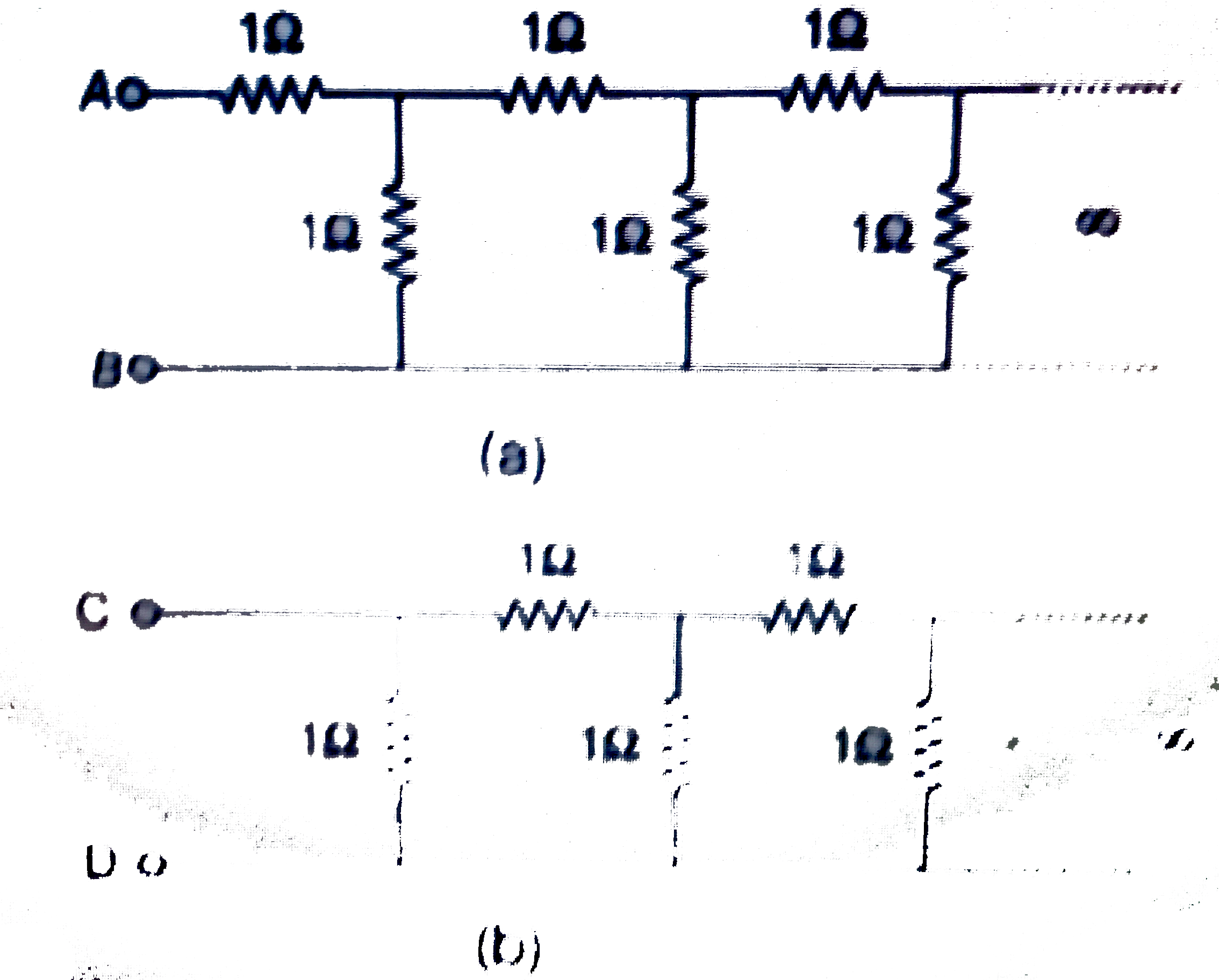 ARAB=RCD=(√3+2)ΩBRAB=(√3+1)ΩCRCD=(√5+1)ΩDRAB>RCD


