Assertion : In a purely inductive or capacitive circuit, the current is referred to as wattless currents.
Reason : No power is dissipated in a purely inductive or capacitive circuit even though a current is flowing in the circuit.
If both assertion ans reason are true ans reaason is the correct explanation of assertion.
If both assertion and reason are true but reason is not the correct explanation of assertion.
If assertion istrue but reason is false.
If both assertion and reason are false.
The correct Answer is:A
To solve the question, we need to analyze the assertion and the reason provided.
1. Understanding the Assertion:
- The assertion states that in a purely inductive or capacitive circuit, the current is referred to as wattless currents.
- Wattless currents are defined as currents that do not result in power dissipation in the circuit.
Hint: Recall the definition of wattless currents and their significance in AC circuits.
2. Understanding the Reason:
- The reason provided states that no power is dissipated in a purely inductive or capacitive circuit, even though a current is flowing in the circuit.
- In AC circuits, power (P) is given by the formula:
P=VrmsIrmscosϕ
- Here, ϕ is the phase angle between the voltage and current.
Hint: Consider how the phase angle affects power dissipation in inductive and capacitive circuits.
3. Analyzing Power in Purely Inductive and Capacitive Circuits:
- In a purely inductive circuit, the current lags the voltage by 90∘ (or π2 radians), which means cos(π2)=0.
- In a purely capacitive circuit, the current leads the voltage by 90∘ (or π2 radians), which also results in cos(π2)=0.
- Therefore, substituting ϕ=π2 in the power formula gives:
P=VrmsIrms⋅0=0
- This indicates that no power is dissipated in these circuits.
Hint: Think about the implications of the phase relationship between current and voltage in determining power.
4. Conclusion:
- Since both the assertion and the reason are true, and the reason correctly explains the assertion, we conclude that:
- Assertion: True
- Reason: True and explains the assertion.
Final Answer: Both assertion and reason are true, and the reason is the correct explanation of the assertion.
- The assertion states that in a purely inductive or capacitive circuit, the current is referred to as wattless currents.
- Wattless currents are defined as currents that do not result in power dissipation in the circuit.
- The reason provided states that no power is dissipated in a purely inductive or capacitive circuit, even though a current is flowing in the circuit.
- In AC circuits, power (P) is given by the formula:
P=VrmsIrmscosϕ
- Here, ϕ is the phase angle between the voltage and current.
- In a purely inductive circuit, the current lags the voltage by 90∘ (or π2 radians), which means cos(π2)=0.
- In a purely capacitive circuit, the current leads the voltage by 90∘ (or π2 radians), which also results in cos(π2)=0.
- Therefore, substituting ϕ=π2 in the power formula gives:
P=VrmsIrms⋅0=0
- This indicates that no power is dissipated in these circuits.
- Since both the assertion and the reason are true, and the reason correctly explains the assertion, we conclude that:
- Assertion: True
- Reason: True and explains the assertion.
Topper's Solved these Questions
- ALTERNATING CURRENT Book:NCERT FINGERTPS ENGLISHChapter:ALTERNATING CURRENT Exercise:Ac Voltage Applied To A Resistor
Explore 17 Videos
- ALTERNATING CURRENT Book:NCERT FINGERTPS ENGLISHChapter:ALTERNATING CURRENT Exercise:Ac Voltage Applied To A Inductor
Explore 5 Videos
- ALTERNATING CURRENT Book:NCERT FINGERTPS ENGLISHChapter:ALTERNATING CURRENT Exercise:NCERT
Explore 7 Videos
- ATOMS Book:NCERT FINGERTPS ENGLISHChapter:ATOMS Exercise:Assertion And Reason
Explore 15 Videos
Similar Questions
Power dissipated in pure inductance will be-
View SolutionThe current in the circuit will be
View SolutionIn the circuit shown, the current flowing from the battery is

View SolutionIn an AC circuit containing only capacitance the current
View SolutionIn the circuit shown in figure current in the circuit is
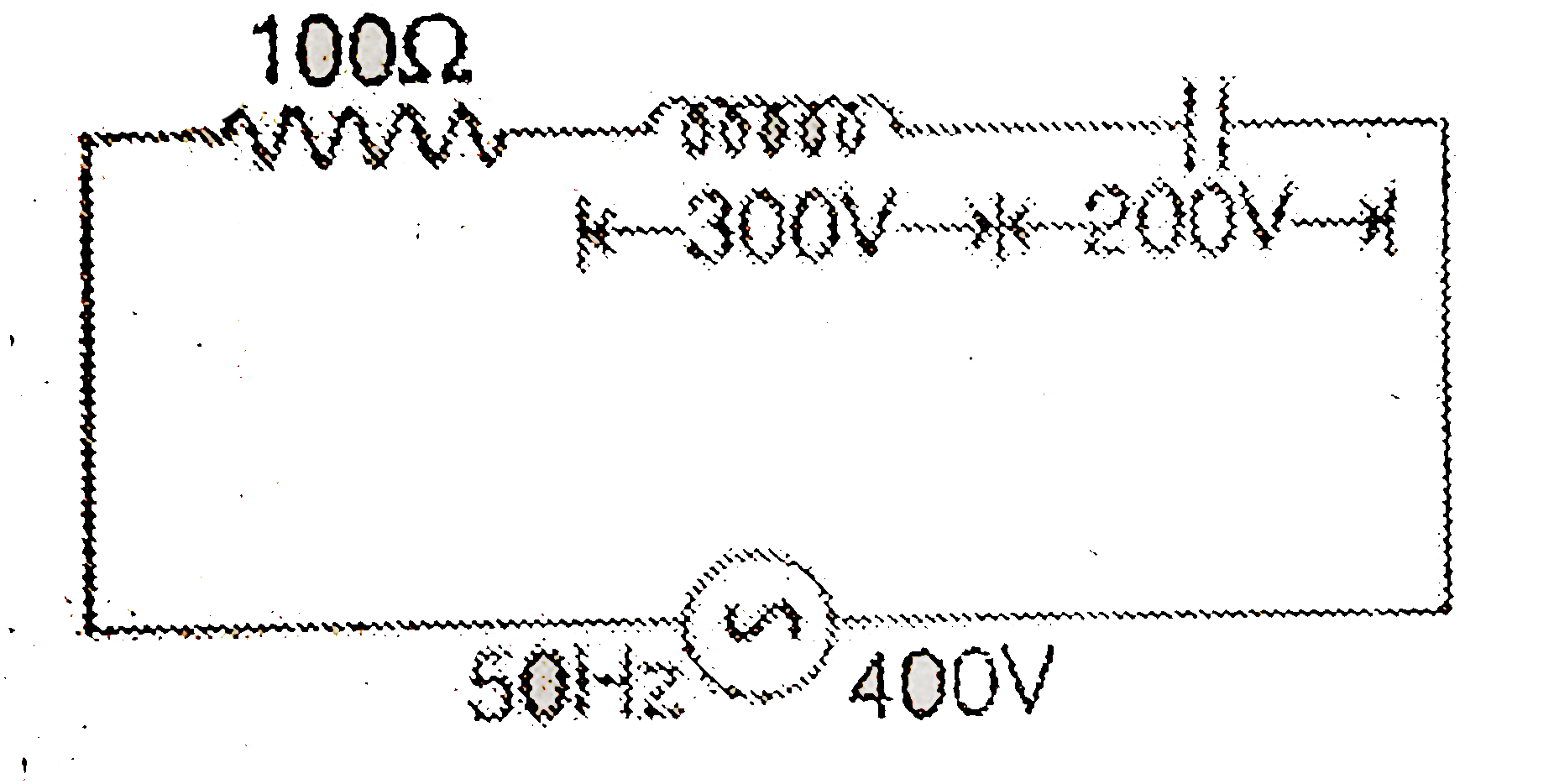
View SolutionCurrent in the circuit will be
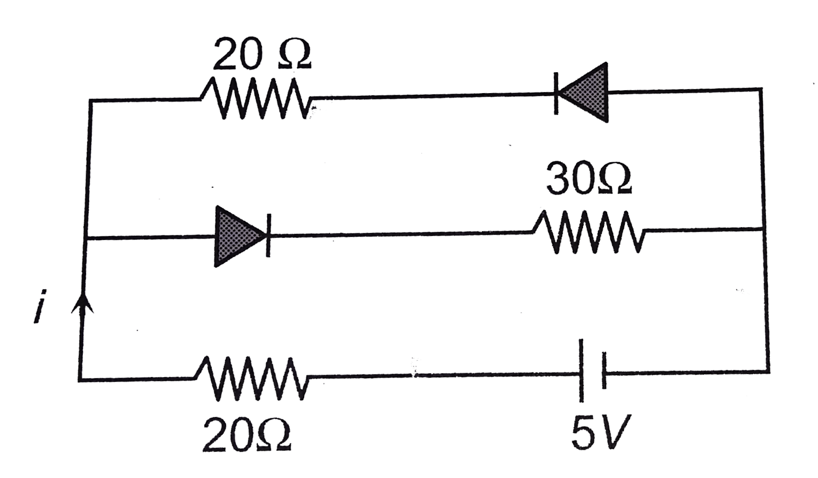
View SolutionIn the circuit shown in figure, the current / in circuit is
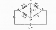
View SolutionIn the circuit, the current flowing through 10Ω resistance is
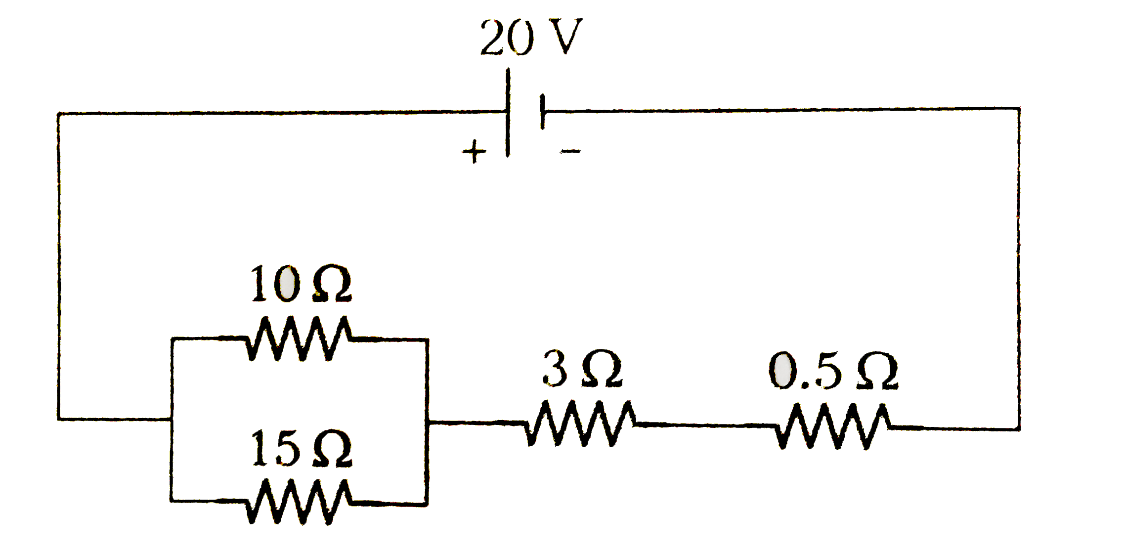
View SolutionThe current flowing through the cell in the circuit shown is
View SolutionIn the circuit in figure, the current flowing 5Ω resistance is :
View Solution