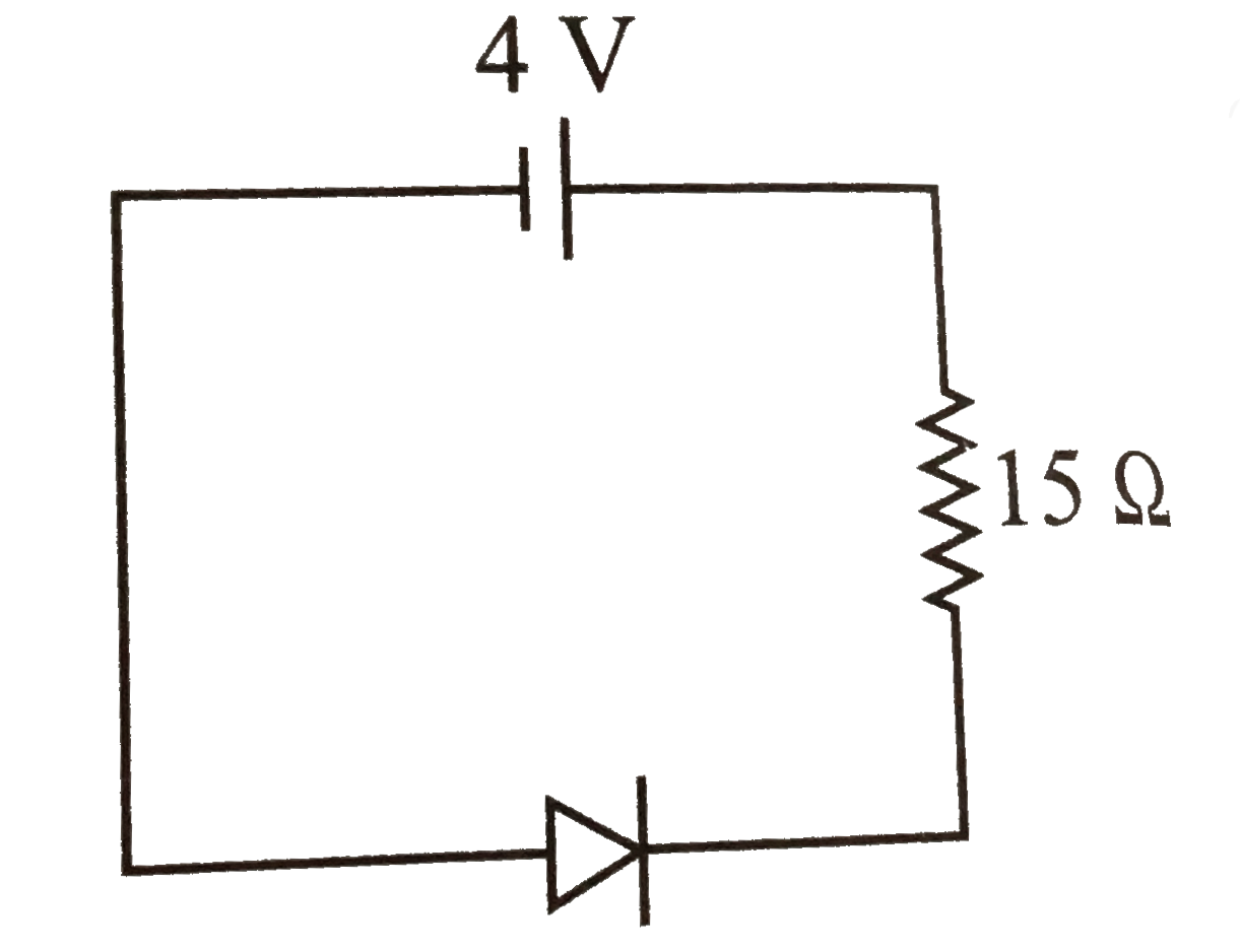
In the circuit shown if current for the diode is 20μA, the potential difference across the diode is
2 V
4.5V
4 V
2.5 V
The correct Answer is:C
Since the diode is reversed biased, only drift current exists in circuit which is 20μA
Potential drop across 15Ω resistor=15Ω×20μA=300μV=0.0003V
Potential difference across the diode = 4 -0.0003 = 3.99 = 4V.
Topper's Solved these Questions
- BOOK - NCERT FINGERTPS ENGLISHCHAPTER - SEMICONDUCTOR ELECTRONICS : MATERIALS , DEVICES AND SIMPLE CIRCUITS EXERCISE - HOTS8videos
SEMICONDUCTOR ELECTRONICS : MATERIALS , DEVICES AND SIMPLE CIRCUITS
- BOOK - NCERT FINGERTPS ENGLISHCHAPTER - SEMICONDUCTOR ELECTRONICS : MATERIALS , DEVICES AND SIMPLE CIRCUITS EXERCISE - NCERT8videos
SEMICONDUCTOR ELECTRONICS : MATERIALS , DEVICES AND SIMPLE CIRCUITS
- BOOK - NCERT FINGERTPS ENGLISHCHAPTER - RAY OPTICS AND OPTICAL INSTRUMENTSEXERCISE - NCERT Exemplar11videos
RAY OPTICS AND OPTICAL INSTRUMENTS
- BOOK - NCERT FINGERTPS ENGLISHCHAPTER - WAVE OPTICSEXERCISE - Assertion And Reason15videos
WAVE OPTICS
Similar Questions
Knowledge Check
- Question 1 - Select One
In the circuit, Fig The current through the zener diode is
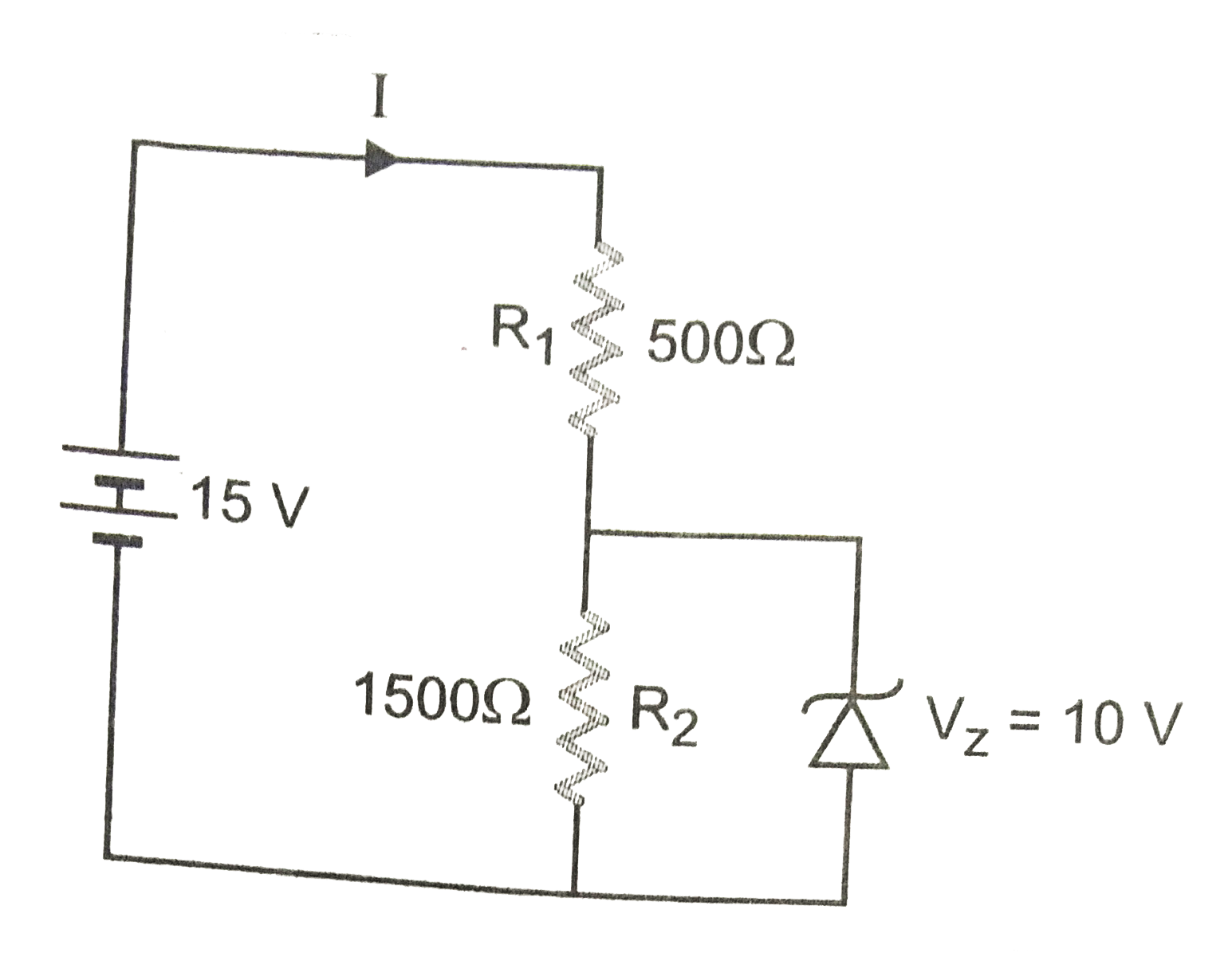 A10 mAB6.67 mAC5 mAD3.33 mA
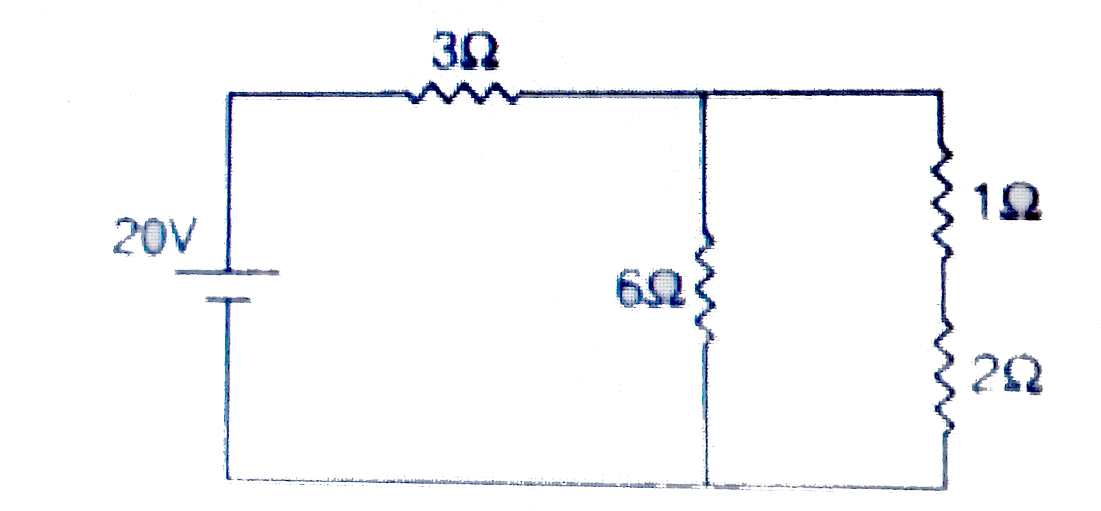
In the circuit shown in figure potential difference across
 View Solution
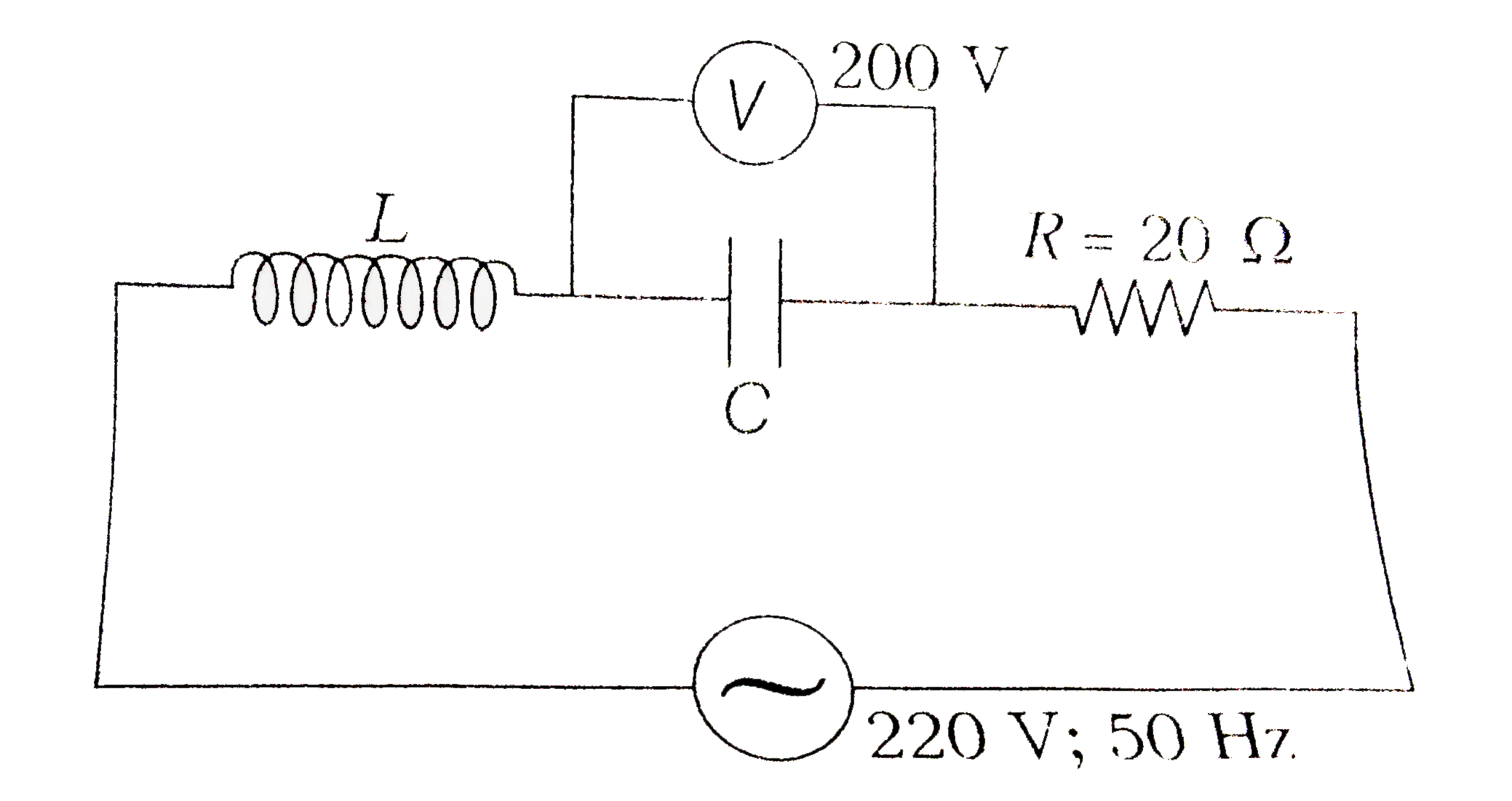
In the circuit shown, rms circuit is 11 A . The potential difference across the inductor is
 View Solution
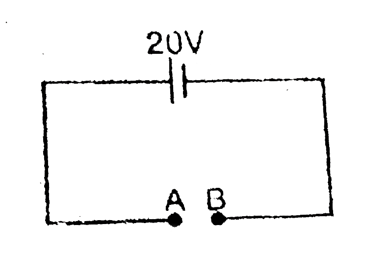
In the shown circuit, what is the potential difference across A and B
 View Solution
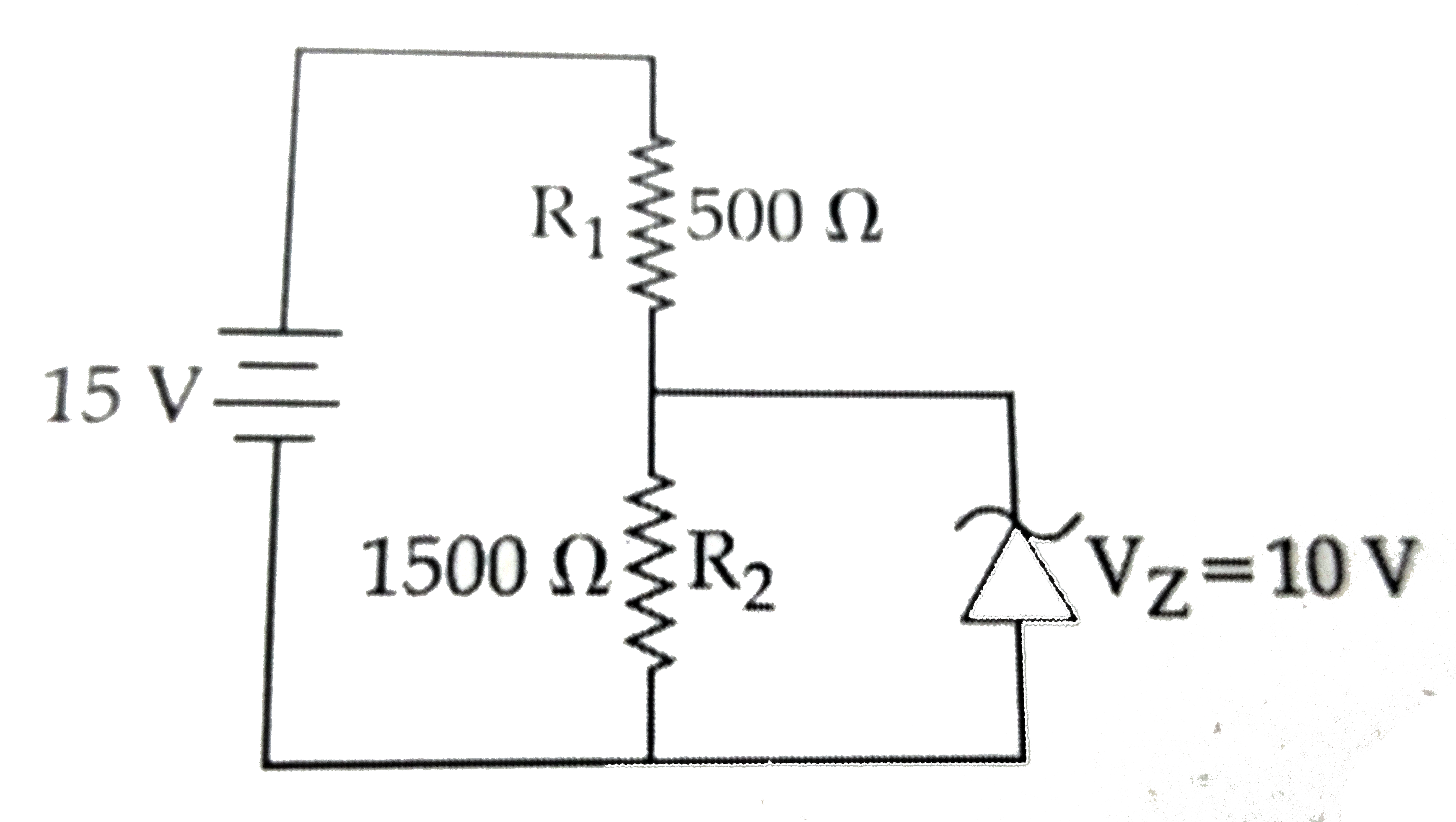
In the given circuit, the current through zener diode is :
 View Solution
In the given circuit, with steady current, the potential difference across the capacitor is
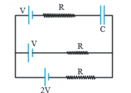 View Solution
In the given circuit, calculate -
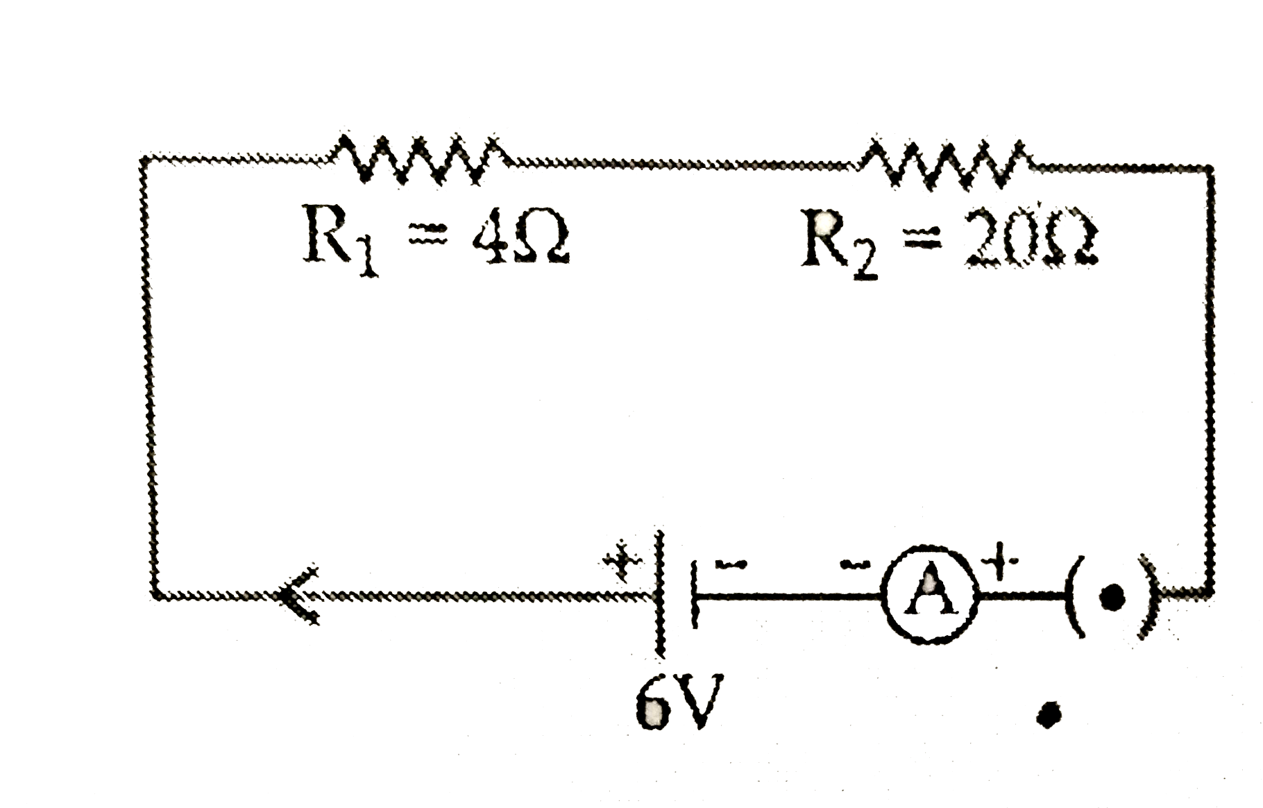
(a) the total resistance of the circuit,
(b) the current through the circuit, and
(c) the potential differences across R1andR2View SolutionIn the circuit shown in Fig. 4.41, calculate the current in each resistor and potential difference across each resistor.
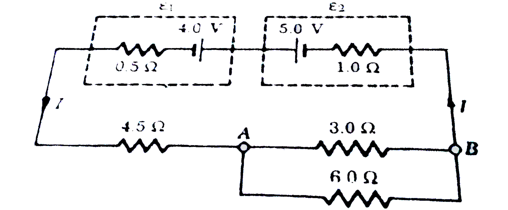 View Solution


