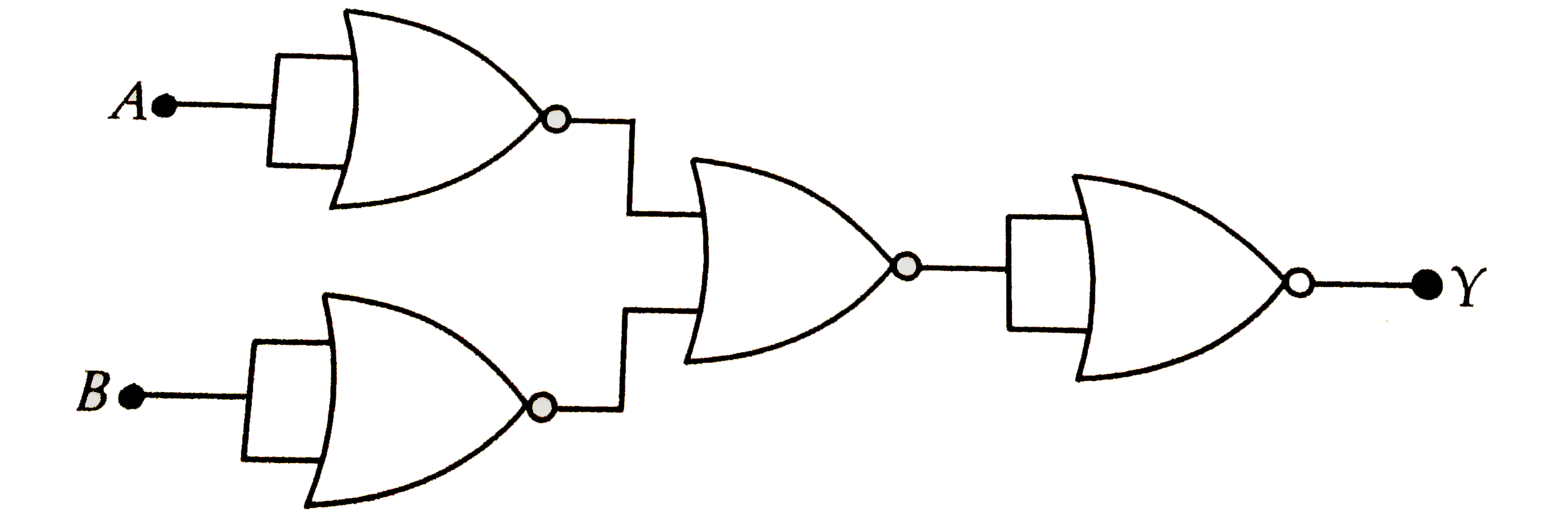
The circuit given in figure, is equivalent to

AND gate
OR gate
NOT gate
NAND gate
The correct Answer is:A
The output of circuit,
Therefore, output is equivalent to AND gate.
Topper's Solved these Questions
- BOOK - NCERT FINGERTPS ENGLISHCHAPTER - SEMICONDUCTOR ELECTRONICS : MATERIALS , DEVICES AND SIMPLE CIRCUITS EXERCISE - HOTS8videos
SEMICONDUCTOR ELECTRONICS : MATERIALS , DEVICES AND SIMPLE CIRCUITS
- BOOK - NCERT FINGERTPS ENGLISHCHAPTER - SEMICONDUCTOR ELECTRONICS : MATERIALS , DEVICES AND SIMPLE CIRCUITS EXERCISE - NCERT8videos
SEMICONDUCTOR ELECTRONICS : MATERIALS , DEVICES AND SIMPLE CIRCUITS
- BOOK - NCERT FINGERTPS ENGLISHCHAPTER - RAY OPTICS AND OPTICAL INSTRUMENTSEXERCISE - NCERT Exemplar11videos
RAY OPTICS AND OPTICAL INSTRUMENTS
- BOOK - NCERT FINGERTPS ENGLISHCHAPTER - WAVE OPTICSEXERCISE - Assertion And Reason15videos
WAVE OPTICS
Similar Questions
Knowledge Check
- Question 1 - Select One
The circuit as shown in the figure is equivalent to
 AAND gateBNOT gateCOR gateDNAND gate
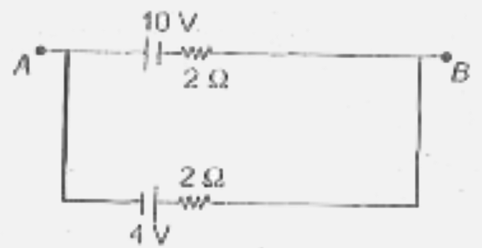
The situation shown in figure is equivalent to
 View Solution
For the circuit shown in figure, the equivalent capacitance of the combination is
 View Solution
Each resistance of the circuit shown in figure is r. The equivalent resistance between A and B is
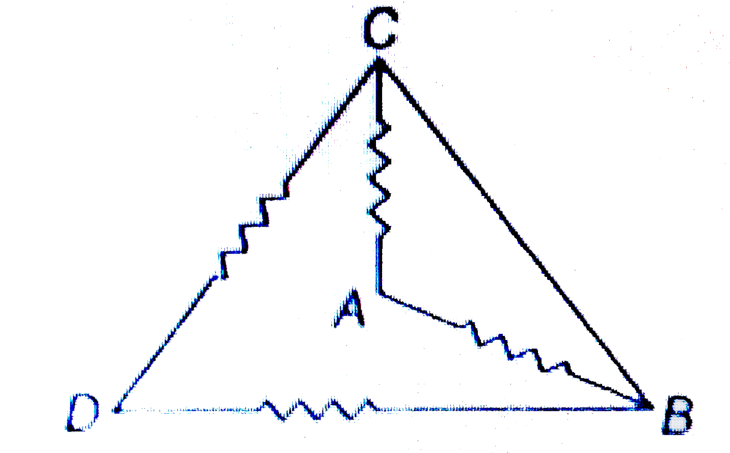 View Solution
In the circuit shown in figure, the equivalent capacitance between the points X and Y is
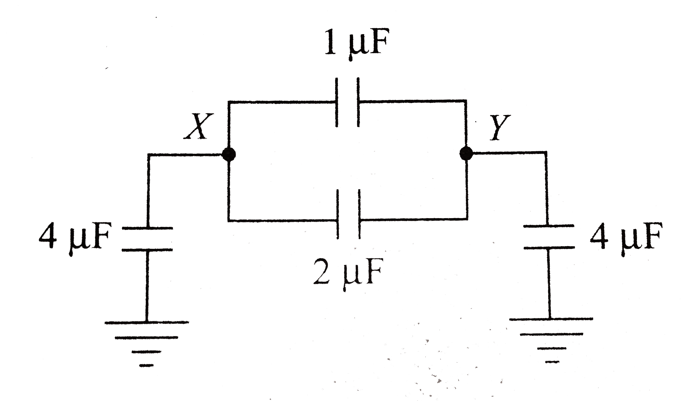 View Solution
In the circuit shown in figure, the equivalent resistance between A and B is __________ Ω.
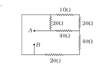 View Solution
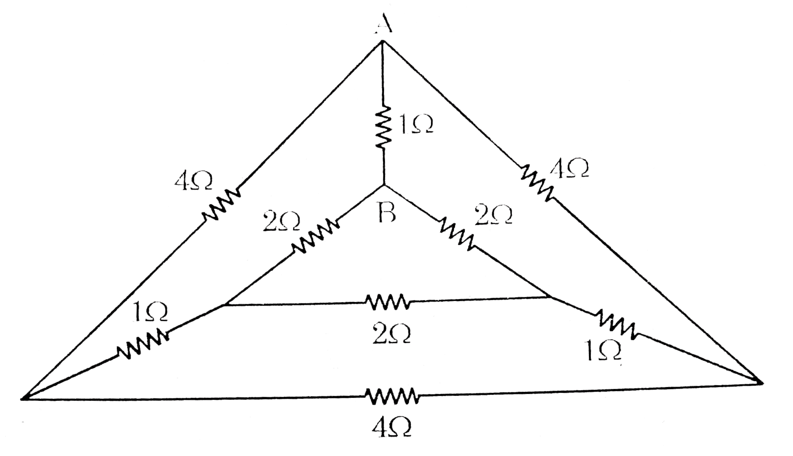
Consider the circuit as shown in figure. The equivalent resistance between A and B is
 View Solution
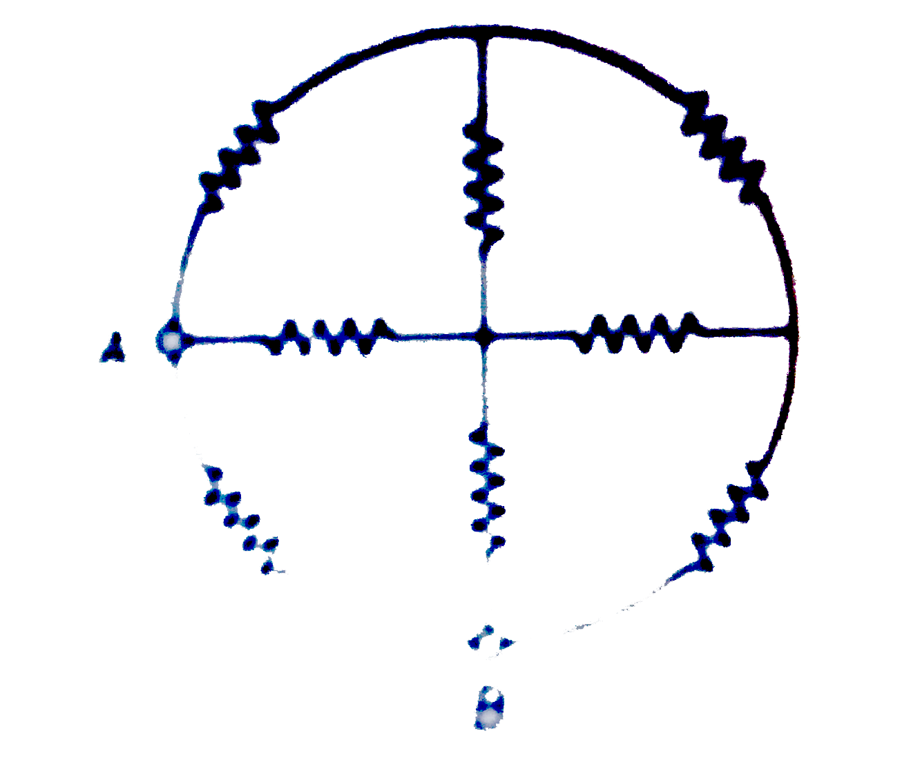
Eight resistances each of resistance 5Ω are connected in the circuit as shown in figure. The equivalent resistance between A and B is
 View Solution


