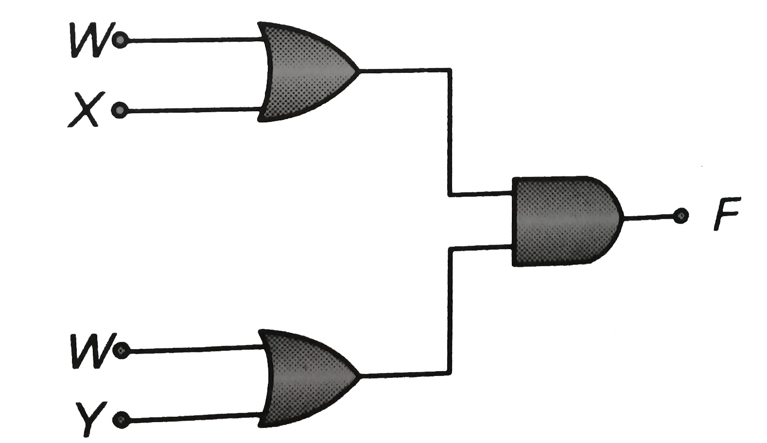
The diagram of a logic circuit is given below. The output F of the circuit is represented by
A
W.(X+Y)
B
W.(X.Y)
C
W+(X.Y)
D
W+(X+Y)
Video Solution
Text Solution
The correct Answer is:C
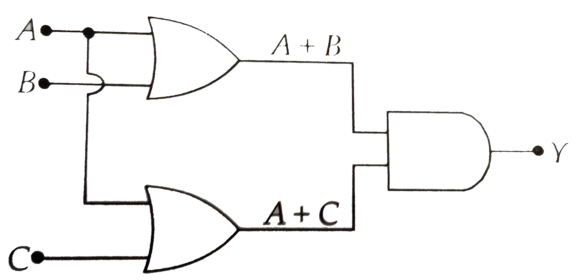
The output of the above logic circuit is Y=(A+B).(A+C)
|
Topper's Solved these Questions
- SEMICONDUCTOR ELECTRONICS : MATERIALS , DEVICES AND SIMPLE CIRCUITS BOOK - NCERT FINGERTPS ENGLISHCHAPTER - SEMICONDUCTOR ELECTRONICS : MATERIALS , DEVICES AND SIMPLE CIRCUITS EXERCISE - HOTS
8 Videos
- SEMICONDUCTOR ELECTRONICS : MATERIALS , DEVICES AND SIMPLE CIRCUITS BOOK - NCERT FINGERTPS ENGLISHCHAPTER - SEMICONDUCTOR ELECTRONICS : MATERIALS , DEVICES AND SIMPLE CIRCUITS EXERCISE - NCERT
8 Videos
- RAY OPTICS AND OPTICAL INSTRUMENTSBOOK - NCERT FINGERTPS ENGLISHCHAPTER - RAY OPTICS AND OPTICAL INSTRUMENTSEXERCISE - NCERT Exemplar
11 Videos
- WAVE OPTICSBOOK - NCERT FINGERTPS ENGLISHCHAPTER - WAVE OPTICSEXERCISE - Assertion And Reason
15 Videos
Similar Questions
Knowledge Check
The output of the given circuit in figure given below,
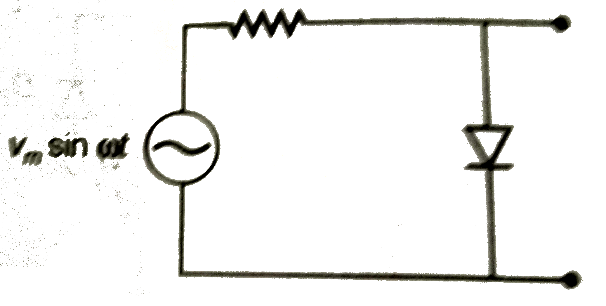 Awould be zero at all times.Bwould be like a half wave rectifier with positive cycles in outputCwould be like a half wave rectifier with negative cycles in output.Dwould be like that of a full wave rectifier.
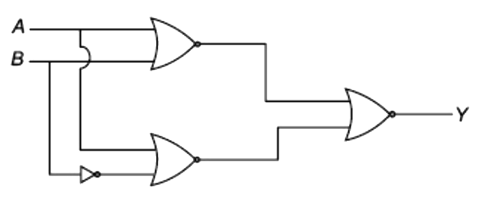
The output of the given logic circuit is
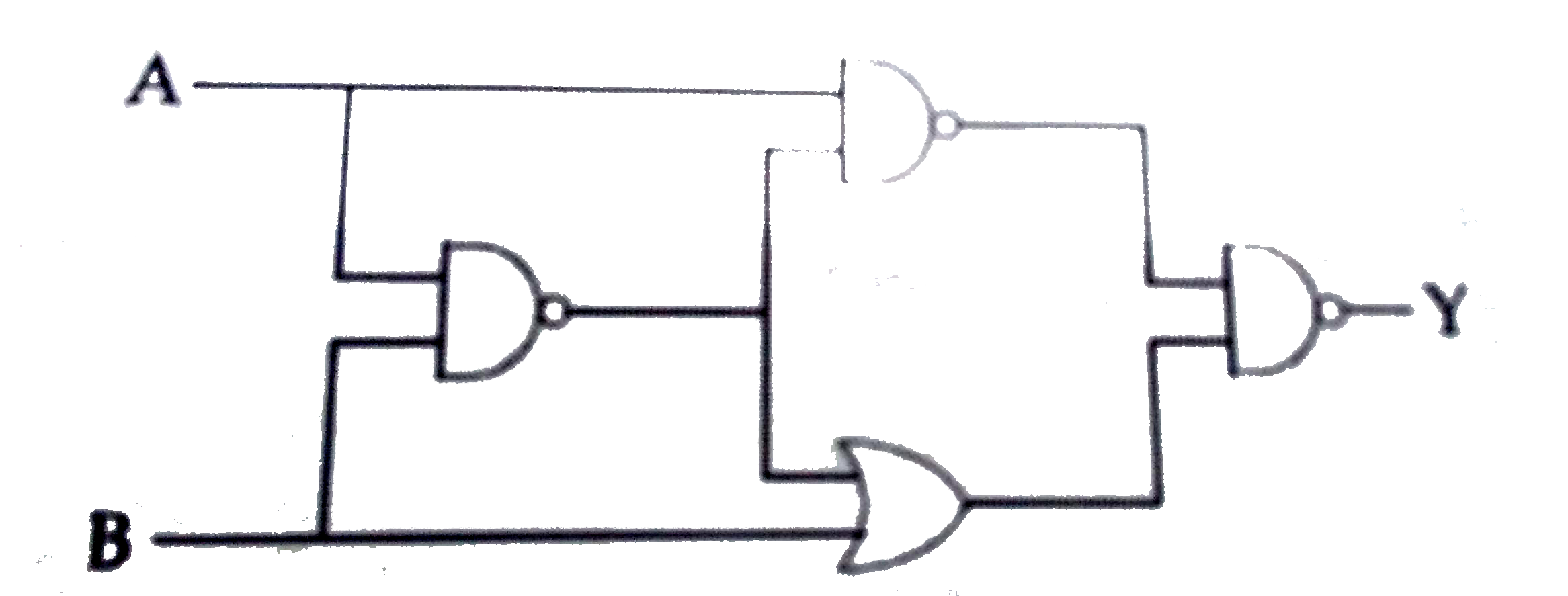
View Solutionthe output given logic circuit is :
View SolutionIn the circuit given below, the value of the current is

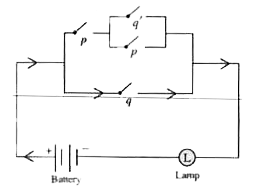
View SolutionThe symbolic form of logic of the circuit given below is
View SolutionThe output of the given logic gate is

View SolutionThe output of the following logic circuit is

View SolutionThe output of the given circuit in figure given below,

View Solution


