Obtain the answers (a) to (b) in Exercise 7.13 if the circuit is connected to a high frequency supply (240 V, 10 kHz). Hence, explain the statement that at very high frequency, an inductor in a circuit nearly amounts to an open circuit. How does an inductor behave in a d.c. circuit after the steady state ?
Here L=0.5H,R=100Ω,Vrms=240V and v= 10 kHz =104 Hz
∴ω=2πv=2×3.14×104=6.28×10⁴s−1
(a) ∴ Impedance Z=√R2+(Lω)2=√(100)2+(0.5×6.28×104)2=3.14×10⁴Ω
∴Im=VmZ=√2VrmsZ=√2×240=1.1×10⁻²A
(b) ϕ=tan−1(OLω)R=tan−1(0.5×6.28×104)100=tan−1(31.4)=π2 rad
∴t=ϕ2πv=π2×2π×6.28×104=4.0×10⁻⁶ s.
From these calculations, it is clear that for a high frequency, current is very very small i.e., at high frequencies the inductor behaves as if the circuit is an open circuit or its impedance is extremely high.
An inductor offers zero resistance in a d.c. circuit after the steady state is reached.
Topper's Solved these Questions
- ALTERNATING CURRENT BOOK - U-LIKE SERIESCHAPTER - ALTERNATING CURRENT EXERCISE - CASE BASED/SOURCE-BASED INTEGRATED QUESTIONS
19 Videos
- ALTERNATING CURRENT BOOK - U-LIKE SERIESCHAPTER - ALTERNATING CURRENT EXERCISE - MULTIPLE CHOICE QUESTIONS
34 Videos
- ALTERNATING CURRENT BOOK - U-LIKE SERIESCHAPTER - ALTERNATING CURRENT EXERCISE - SELF ASSESSMENT TEST (SECTION -C)
2 Videos
- ATOMSBOOK - U-LIKE SERIESCHAPTER - ATOMSEXERCISE - SELF ASSESSMENT TEST (SECTION C)
2 Videos
Similar Questions
Obtain the answers to (a) and (b) Q.13, if the circuit is connected to a high frequency supply (240 V , 10 kHz). Hence explain statement that at very high frequency. Inductor in circuit nearly amount to open circuit. How does an indcutor behave in a d.c. circuit after the steady state ?
View SolutionObtain the answers to (a) and (b) Q.13, if the circuit is connected to a high frequency supply (240 V , 10 kHz). Hence explain statement that at very high frequency. Inductor in circuit nearly amount to open circuit. How does an indcutor behave in a d.c. circuit after the steady state ?
View Solution
Knowledge Check
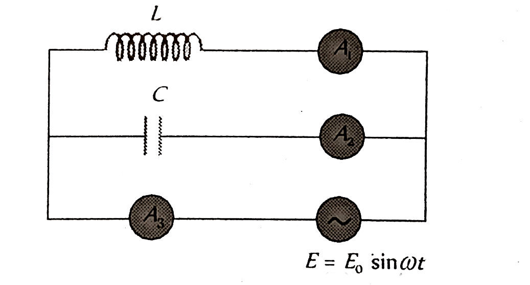
An inductor L and a capacitor C are connected in the circuit as shown in the figure. The frequency of the power supply is equal to the resonant frequency of the circuit. Which ammeter will read zero ampere
 AA1BA2CA3DNone of these
A capacitor of capacitance 25μF is charged to 300V. It is then connected across a 10mH inductor. The resistance in the circuit is negligible.
a. Find the frequency of oscillation of the circuit.
b. Find the potential difference across capacitor and magnitude of circuit current 1.2ms after the inductor and capacitor are connected.
c. Find the magnetic energy and electric energy at t=0 and t=1.2ms.A318.3Hz 221.2volt , 10.13AB318.3Hz 221.2volt , 7.13AC328.3Hz 221.2volt , 10.13AD118.3Hz 221.2volt , 10.13A
Obtain the answers to (a) and (b) above in Exercise 7.15 if the circuit is connected to a 110 V, 12 kHz supply ? Hence, explain the statement that a capacitor is a conductor at very high frequencies. Compare this behaviour with that of a capacitor in a d.c. circuit after the steady state
View SolutionObtain the answers to (a) and (b) in Q .15, if the circuit is connected to 110 V, 12 kHz supply. Hence explain the statement that a capacitor is a conductor at very high frequencies. Compare this behaviour with that of a capacitor in d.c. after the steady state.
View SolutionAn inductor L and a capacitor C are connected in the circuit as shown in the figure. The frequency of the power supply is equal to the resonant frequency of the circuit. Which ammeter will read zero ampere

View SolutionA series LCR circuit with r=10ohm,L=2H and C=25μF is connected to a varialbe frequency 200 V a.c. supply. When the frequency of the supply equals the natural frequency of the circuit, what is the average power transferred to the circuit in one complete cycle ?
View SolutionA capacitor of capacitance 25μF is charged to 300V. It is then connected across a 10mH inductor. The resistance in the circuit is negligible.
a. Find the frequency of oscillation of the circuit.
b. Find the potential difference across capacitor and magnitude of circuit current 1.2ms after the inductor and capacitor are connected.
c. Find the magnetic energy and electric energy at t=0 and t=1.2ms.
View Solution(a) In a series LCR circuit connected across an a.c. source of variable frequency, obtain the expression for its impedance and draw a plot showing its variation with frequency of the a.c. source.
(b) What is the phase difference between the voltages across inductor and the capacitor at resonance in the LCR circuit ?
(c) When an inductor is connected to a 200 V d.c. voltage, a current of 1 A flows through it. When the same inductor is connected to a 200 V, 50 Hz a.c. source, only 0.5 A current flows. Explain, why ? Also, calculate the self inductance of the inductor.
View Solution
